On Designing Centres
Description
This section is from the book "Elementary Principles Carpentry", by Thomas Tredgold. Also available from Amazon: Elementary Principles Of Carpentry.
On Designing Centres
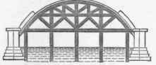
298. A centre should be designed so as to be capable of supporting either a portion or the whole of the weight of the arch without changing its form, and each of its parts should be proportioned according to the pressure, and disposed so as to be free from strains which act too obliquely. 299. Centres for arches of small span are easily managed, and when intermediate supports can be obtained at a com-aratively small expense, even large centres are not difficult to construct. The centering of Conon Bridge (Fig. 90), designed by Telford, of which the span is 65 feet and rise 218 feet, is a good example.
Fig. 1, Plate XXXV., is another design for a centre with intermediate supports, used for a bridge of Telford's over the River Don. of which the span is 75 feet.
Fig. 90.
The centre shown by Fig. 2, Plate XXXV., is perhaps one of the best examples of its kind. It was constructed by Mr. Cargil, the contractor, for a stone bridge at Gloucester, of 150 feet span and 35 feet rise, designed by Telford after Perronet's bridge over the Seine at Neuilly. The mode of execution was as follows: -
Plate XXXV.
CENTRES.
Fig. 1.
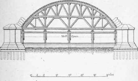
Fig.2.
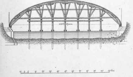
A platform was prepared perfectly level, on which the centre was struck out to the full size. The timber employed was from Dantzic, in scantlings of about 15 inches square. The piles which supported the centre were of Memel, shod and capped with wrought iron. On these were laid a tier of beams lengthways to the centre, one under each rib, and upon these beams the wedges were fixed, which were of three thicknesses, the bottom one being bolted down to the beams; the tongue or driving piece in the middle was of oak, well hooped at the driving end; the top side of the upper piece was laid perfectly level and straight, both transverse and longitudinally. The wedges were rubbed with soft soap and blacklead before they were laid upon each other.
Each rib of the centre was then brought and put together upon a scaffold made upon the top of the wedge pieces, and was lifted up by means of two barges on the river and two cranes on shore.
The scaffold was extended 30 feet beyond the striking end of the wedges, to lay the last ribs upon previously to raising, and for the workmen to stand upon for finally striking. After the ribs were properly braced they were covered with the 4-inch sheeting piles which had been used in the cofferdams.
This centre was so well formed that when the arch was keyed its sinking was not more than an inch, and it was struck in the short space of three hours. This was performed by placing beams upon the top of the work directly over the ends of the wedges to these beams was fixed a tackle, and at its lower end was slung a ram of 12 cwt., which was swung to and fro, so as to strike the driving end of the tougue-piece of the wedge. This operation required eight men to pull it back and two men to bring it forward; after twenty or thirty blows the wedges started; they then moved easily, and pieces were put in to stop their going farther than was required.
The coverings or laggings were then taken off and the ribs were let down in the same order in which they were put up.
The bearing piles were then drawn by two levers, each 42 feet long, and strong chains.
Fig. 91 shows the centre used for Coldstream Bridge, designed by Smeaton, who says of it, " What I had therefore in view was to distribute the supporters equally under the burden, preserving at the same time such a geometrical connection throughout the whole, that if any one pile, or row of piles should settle, the incumbent weight would be supported by the rest.
Fig. 91.
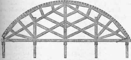
"With respect to the scantling," he adds, "I did not so much contrive how to do with the least quantity of timber, as how to cut it with the least waste; for, as I took it for granted the centre would be constructed with East County fir, I have set down the scantlings, such as they usually are, in whole balks, or cut in two lengthways." *
The bridge was of stone, 25 feet wide from outside to outside; the centering consisted of five ribs framed in the manner represented by Fig. 91. The span of the centre arch was 60 feet 8 inches.
In the construction of the Grosvenor Bridge over the Dee at Chester, erected in 1833, the centre adopted by Mr. Trub-shaw, the contractor, consisted of back pieces in two thicknesses of 4-inch plank following the curve of the arch, supported by a series of struts radiating somewhat similar to that at the Gloucester Bridge (Fig. 2, Plate XXXV.), in a fan-like arrangement, from iron shoes or sockets placed on the tops of temporary stone piers, of which there were four in the total span of 200 feet. The striking wedges, which were similar to those used at Waterloo Bridge (Fig. 2, Plate XXXVI.), were placed immediately under the laggings on the whole round of the arch, so that any portion might be relieved from support while the remainder were still borne by the centre.
Plate XXXVI
CENTRES.
The struts were connected to each other and with those of the adjoining piers by waling pieces bolted to them at distances of from 10 to 12 feet apart vertically.†
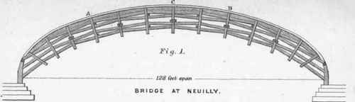
300. Where intermediate supports cannot be obtained the design and execution of a centre becomes much more difficult, owing to the necessity of taking precautions to counteract the tendency of the crown to rise when the load is placed upon the haunches. This cannot be illustrated better than by examining the defects of the centre designed by Perronet for the bridge at Neuilly, as shown by Fig. 1, Plate XXXVI. It is obvious that such a centre loaded at A and B must rise at C, and the timbers being nearly parallel, the strains produced by a weight resting on any point must have been enormous; consequently, the yielding at the joints was very considerable. The system here exhibited is well enough adapted to support an equilibrated load distributed oyer the whole length; but it is one of the worst that could be adopted for a centre which has to support a variable load. An immense quantity of timber must have been consumed without much advantage. It is crowded into so small a space that the centre has a light appearance which has obtained for it the approbation of many, but who were probably incapable of investigating the true principles on which centres should be designed. The centres for the bridges of Nojent Cravant, St. Maxence, and Nemours, were designed on similar principles and were found to be equally defective.
* Smeaton's ' Reports,' vol. iii., p. 236. † ' Trans. Inst. Civ. Eng.,' vol. i.
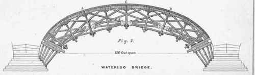
Fig. 2, Plate XXXVI., represents the centre of Waterloo Bridge, designed by Rennie, in which, owing to a better disposition of the timbers, a load at A could not cause the centre to rise at C without reducing the length of the beam D E and that of the one opposite to it. In some of its parts, however, there is an excess of strength besides being very complicated, but on the whole it is not a bad combination. The design appears to have been adapted from the centre used for the late bridge at Blackfriars, designed by Mylne in 1760 - with some improvement both in form and construction - which did much credit to the engineer.
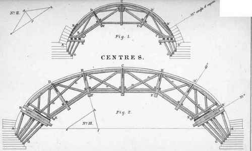
In further illustration of the principle of constructing centres without intermediate supports. Let the line A C A' (Fig. 1, Plato XXXVII.) represent the curve of an arch, and suppose the arch-stones to begin to press upon the centre at B B', where the joints make an angle of 32 degrees with the horizontal plane, and that the laying of the arch-stones proceed simultaneously on each side. Now if two trussed frames E D H, E' D' H', abut against each other at C, the point C cannot rise in any sensible degree from the pressures at D, D', and by adding the piece F F' with the pieces F I, F' I', much additional security will be obtained.
The framing of this centre commences on each side nearly at a point where the arch-stones first begin to press on it. The curved rib must be strong enough to sustain the weight between B D and D C, but the bearings may bo shortened by making the abutting blocks at D. D', longer. The beams E C, E' C, will act as ties until the arch-stones are laid beyond the points D D'; they will then begin to act as struts and will continue so to act until the whole be laid.
This arrangement cannot be economically employed where the span is large, owing to the length of the timbers required.
Again, let the built beams E F, F F', and F' E' (Fig. 2, Plate XXXVII.), be each trussed, and abut against each other at F and F', then it is obvious that when the loads press equally at D D' there will be no tendency in the beam F F' in the middle to rise unless it is too weak to resist the pressure in the direction of its length; and as it is easy to give it any degree of strength that may be required, a centre of this form may, with a little variation, be applied to any span to which a stone bridge can be erected. "When timber of sufficient length is not to be obtained the beams E F, F F', and F' E', may be built in the manner described in another part of this work for building beams.
Plate XXXVII
CENTRES.
As a general rule it is advisable to make the piers support the whole weight of the centering, particularly if the foundations be of a yielding nature, as by this means no additional weight is brought on the foundations after the centre is removed, and consequently there is less likelihood of settlement in the arches.
The girder principle, as applied to timber bridges, may in most cases be used with advantage in the construction of centres.
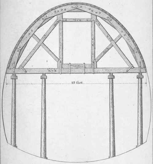
301. Plate XXXVIII. shows the description of centre most frequently adopted for tunnels. The framing is similar in principle to that of a queen-post truss as described in the Section on Roofs. The back pieces of the rib are usually-formed of two thicknesses of 3-inch plank bolted together. The distance apart of the ribs is about 5 feet. When raking struts are required to be used in excavating the tunnel, the two leading ribs, or those next to the excavation, should be constructed without tie-beams, to avoid interfering with the struts.
Plate XXXVIII.
COFFERDAMS.
It is hoped that sufficient information has been given to enable the reader to obtain a clear notion of the arrangement required for the centre of an arch, and that he will have no difficulty in applying the principles here indicated to one of any form or span.
Continue to:
My Books

