Wooden Bridges, Viaducts, Etc. Part 2
Description
This section is from the book "Elementary Principles Carpentry", by Thomas Tredgold. Also available from Amazon: Elementary Principles Of Carpentry.
Wooden Bridges, Viaducts, Etc. Part 2
331. In a bridge constructed near Etringen, by Wiebe-king, of which the span was 139 feet and the rise 8 feet, the following method of providing against lateral motion was adopted. Two ribs were placed parallel to each other at the sides of the bridge, and two other ribs were placed diagonally between them, so as to cross in the centre of the bridge.* This method of placing the ribs rendered braces in the flooring unnecessary.
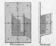
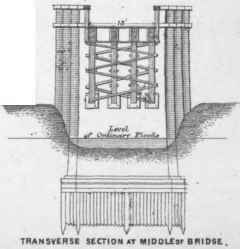
332. Some very light and elegant wooden bridges were erected by James Burn, of Haddington: the largest was over the river Don, seven miles from Aberdeen. The span of this bridge was 109 feet 3 inches, and rise 13 feet 4 inches; the radius of curvature, 119 feet, and the width of the roadway 18 feet.†
333. Plate XLI. shows a timber bridge of 100 feet span, erected by Telford over the river Spey at Laggan Kirk. The arrangement is a judicious one for moderate spans, but the abutments should be made sufficiently strong to resist the thrust of the raking struts which support nearly the whole weight of the bridge and its load. Bridges on this principle have been used on the Drammen Randstjord Railway in Norway for spans of 50 and 80 feet.* The design is however, better adapted for common roads, where the traffic is light and where the heavier loads move slowly, than for railways, where heavy loads move at a great speed.†
Plate XLI.
BRIDGES.


SOCKET AT A
SOCKET AT B
* From Wiebeking, 'Traite dune Partie essentielle de la Science de Construire les Ponts.' † ' Edinburgh Encyclopaedia,' art. Bridge.
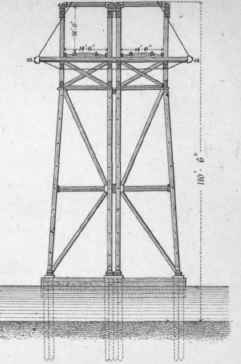
334. A novel combination of iron with wood is shown by Plate XLII, which is the main truss of a viaduct, designed by I. K. Brunei, to carry the South Wales Railway over the valley of the river Tawe, near the village of Landore; completed in 1850. The entire length of the viaduct is 1760 feet, and the span of the truss shown in Plate XLII, which is that over the river, is 110 feet.
Plate XLII
BRIDGES .
Fiq.1.

LANDORE viaduct.
Fig.2.
On account of the headway required for the traffic on the river, this truss was placed above the railway. The other trusses, which were of smaller span, were placed under the railway.
The viaduct is terminated at both ends by abutments of masonry. Several of the intermediate supports or piers were formed of timber, as the treacherous nature of the ground rendered it difficult to erect piers of masonry that would stand.
The truss shown by Fig. 1, Plate XLII, is arranged in two rings or series in the form of a polygon, one inside the other, and braced by wrought-iron tie-bars. All the struts in the truss were built of double timbers, each 13 inches by 14 inches, bolted together by 1-inch bolts, about 2 feet 6 inches apart. The struts fit into cast-iron shoes, to which wrought-iron straps are attached, and which perform the respective duties of suspending and main tie-bars. There are two entire sets of straps, one on each side
* ' Engineering,' Jan. 13, 1871. † ' Telford's Life and Works.' of the truss; the suspending straps on which the roadway is hung being connected to the longitudinal timbers which support the flooring by wrought-iron saddles, which pass underneath the timbers.
The main tie-bar, which is 6 inches by 1 1/2 inch, is in three lengths, the centre length being drawn up 6 feet 6 inches above the level of the springing to give headway over the river. The suspending straps are 4 inches by 1 inch in cross section, each strap being fitted with two gib-keys and two small cottars, to permit of adjustment. The cottars are kept in position by a bolt passing through them. This was considered preferable to having one through-key, as an opportunity was afforded for correcting any unequal length in the straps. The piers or supports for the truss shown on Plate XLII. were formed of four pieces of timber, each 13 inches square. Three of them were bolted together by 1 1/2 inch bolts, and are perpendicular in elevation, whilst the fourth spreads away from the other at an inclination of 1 in 10, and thus forms a fore-and-aft abutment for the main leg. They are all fitted into cast-iron shoes at the bottom, resting on oak sills laid on piles, which are waled on the face for protection against the river traffic. Fig. 2 shows the method of connecting the legs under the roadway.
There are four of these trusses in the width of the roadway, as shown by Fig. 2, Plate XLII., viz. two for the up line, and two for the down line, and they are arranged so that each roadway is complete in itself, by which either pair of trusses can be removed, if necessary, without stopping the passage of the trains. A flooring 8 inches thick is laid across the four trusses, and is supported by the longitudinal timbers which are suspended by the straps already described.
To unite the trusses, four struts, each 12 inches square, two to each truss, are dropped into pockets prepared in the castings, at the crown of the truss, at a sufficient height above the line of rails to allow the trains to pass under them; and two bolts, 1 inch diameter, one on each side of each strut, and through the castings, unite the trusses of each pair; the pairs of trusses are connected together by bolts and blocking pieces similar to those used for the legs.
The trusses are stiffened transversely by a set of diagonal struts, 8 inches by 8 inches, under the flooring, and directly over the legs; but the trusses depend mainly for their transverse support on a diagonal outriding tie-rod, shown at a in Fig. 2.
On the whole, this viaduct shows one of the best methods of combining wood with iron in bridges for railway purposes.*
Continue to:
My Books

