Compression Across The Grain
Description
This section is from the book "The Mechanical Properties Of Wood", by Samuel J. Record. Also available from Amazon: The Mechanical Properties Of Wood.
Compression Across The Grain
Apparatus: An ordinary static testing machine, a bearing plate, and a deflectometer are required. (See Fig. 35.)
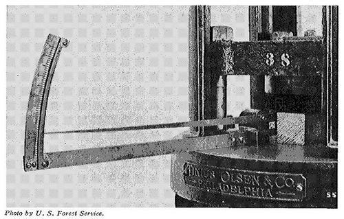
Figure 35
Compression across the grain. Note method of measuring the deformation by means of a deflectomoter.
Preparing the material: Two classes of specimens are used, namely, (1) sections of commercial sizes of ties, beams, and other timbers, and (2) small, clear specimens with the length several times the width. Sometimes small cubes are tested, but the results are hardly applicable to conditions in practice. In (2) the sides are surfaced and the ends squared. The specimens are then carefully measured and weighed, defects noted, rate of growth and proportion of late wood determined, as in bending tests. (See page 95.) After the test a moisture section is cut and weighed.
Sketching: Sketches are made as in endwise compression tests. (See page 102.)
Adjusting specimen in machine: The specimen is laid horizontally upon the platform of the machine and a steel bearing plate placed on its upper surface immediately beneath the centre of the movable head. For the larger specimens this plate is six inches wide; for the smaller sizes, two inches wide. The plate in all cases projects over the edges of the test piece, and in no case should the length of the latter be less than four times the width of the plate.
Measuring the deformation: The compression is measured by means of a deflectometer (see Fig. 35), which, after the first increment of load is applied, is adjusted (by means of a small set screw) to read zero. The actual downward motion of the movable head (corresponding to the compression of the specimen) is multiplied ten times on the scale from which the readings are made.
Log of the test: The load is applied continuously and at uniform speed (see Speed of Testing Machine, page 92), until well beyond the elastic limit. The compression readings are taken at regular load increments and entered on the cross-section paper in the usual way. Usually there is no real maximum load in this case, as the strength continually increases as the fibres are crushed more compactly together.
Calculating the results: Ordinarily only the fibre stress at the elastic limit (c) is computed. It is equal to the load at elastic limit (P) divided by the area under the plate (B).
| ( | P | ) | ||
| c | = | ------- | ||
| B |
Continue to:
My Books

