Endwise Compression
Description
This section is from the book "The Mechanical Properties Of Wood", by Samuel J. Record. Also available from Amazon: The Mechanical Properties Of Wood.
Endwise Compression
Apparatus: An ordinary static testing machine and a compressometer are required. (See Fig. 33.)
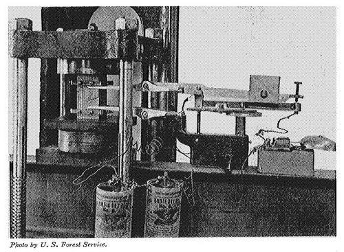
Figure 33
Endwise compression test, showing method of measuring the deformation by means of a compressometer.
Preparing the material: Two classes of specimens are commonly used, namely, (1) posts 24 inches in length, and (2) small clear blocks approximately 2" × 2" × 8". The specimens are surfaced on all four sides and both ends squared smoothly and evenly. They are carefully weighed, measured, rate of growth and proportion of late wood determined, as in bending tests. After the test a moisture section is cut and weighed. Ordinarily these specimens should be free from defects.
Sketching: Sketches are made of each end of the specimens to show the character of the growth. After testing, the manner of failure is shown for all four sides, and the various parts of the failure are numbered in the order of their occurrence.
Adjusting specimen in machine: The compressometer collars are adjusted, the distance between them being 20 inches for the posts and 6 inches for the blocks. If the two ends of the blocks are not exactly parallel a ball-and-socket block can be placed between the upper end of the specimen and the movable head of the machine to overcome the irregularity. If the blocks are true they can simply be stood on end upon the platform and the movable head allowed to press directly upon the upper end.
Measuring the deformation: The deformation is measured by a compressometer. (See Fig. 33.) The latter registers to 0.001 inch. In the case of posts the compression between the collars is communicated to the four points on the arms by means of brass rods; with short blocks, as in Fig. 33, the points of the arms are in direct contact with the collars. The operator lowers the fulcrum of the apparatus by moving the micrometer screws at such a rate that the set-screw in the rear end of the upper lever is kept barely touching the fixed arm below it, being guided by a bell operated by electric contact.
Log of the test: The load is applied continuously at a uniform rate of speed. (See Speed of Testing Maching, page 92.) Readings are taken from the scale of the compressometer at regular increments of either load or compression. The stress-strain diagram is continued to at least one deformation point beyond the maximum load, and in event of sudden failure, the direction of the curve beyond the maximum point is indicated. A brief description of the failure is entered on the log sheet. (See Fig. 34.)

Figure 34
Sample log sheet of an endwise compression test on a short pine column.
In short specimens the failure usually occurs in one or several planes diagonal to the axis of the specimen. If the ends are more moist than the middle a crushing may occur on the extreme ends in a horizontal plane. Such a test is not valid and should always be culled. If the grain is diagonal or the stress is unevenly applied a diagonal shear may occur from top to bottom of the test specimen. Such tests are also invalid and should be culled. When the plane (or several planes) of failure occurs through the body of the specimen the test is valid. It may sometimes be advantageous to allow the extreme ends to dry slightly before testing in order to bring the planes of failure within the body. This is a perfectly legitimate procedure provided no drying is allowed from the sides of the specimen, and the moisture disk is cut from the region of failure.
Calculating the results: The formulæ used in calculating the results of tests on endwise compression are as follows:
| P | |||
| (1) | C | = | ----- |
| A | |||
| P | |||
| (2) | c | = | ------- |
| A | |||
| P l | |||
| (3) | E | = | --------- |
| A D | |||
| P D | |||
| (4) | S | = | ----- |
| 2 V | |||
| C | = | crushing strength, pounds per square inch. | |
| c | = | fibre strength at elastic limit, pounds per square inch. | |
| A | = | area of cross section, square inches. | |
| l | = | distance between centres of collars, inches. | |
| D | = | total shortening at elastic limit, inches. | |
| V | = | volume of specimen, cubic inches. |
Remainder of legend as on page 98.
Continue to:
My Books

