Compressive Or Crushing Strength
Description
This section is from the book "The Mechanical Properties Of Wood", by Samuel J. Record. Also available from Amazon: The Mechanical Properties Of Wood.
Compressive Or Crushing Strength
Compression across the grain is very closely related to hardness and transverse shear. There are two ways in which wood is subjected to stress of this kind, namely, (1) with the load acting over the entire area of the specimen, and (2) with a load concentrated over a portion of the area. (See Fig. 2.) The latter is the condition more commonly met with in practice, as, for example, where a post rests on a horizontal sill, or a rail rests on a cross-tie. The former condition, however, gives the true resistance of the grain to simple crushing.]

Figure 2
Compression across the grain.
The first effect of compression across the grain is to compact the fibres, the load gradually but irregularly increasing as the density of the material is increased. If the specimen lies on a flat surface and the load is applied to only a portion of the upper area, the bearing plate indents the wood, crushing the upper fibres without affecting the lower part. (See Fig. 3.) As the load increases the projecting ends sometimes split horizontally. (See Fig. 4.) The irregularities in the load are due to the fact that the fibres collapse a few at a time, beginning with those with the thinnest walls. The projection of the ends increases the strength of the material directly beneath the compressing weight by introducing a beam action which helps support the load. This influence is exerted for a short distance only.
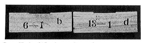
Figure 3
Side view of failures in compression across the grain, showing crushing of blocks under bearing plate. Specimen at right shows splitting at ends.

Figure 4
End view of failures in compression across the grain, showing splitting of the ends of the test specimens.
| TABLE IV | ||
|---|---|---|
| RESULTS OF COMPRESSION TESTS ACROSS THE GRAIN ON 51 WOODS IN GREEN CONDITION, AND COMPARISON WITH WHITE OAK | ||
| (U. S. Forest Service) | ||
| COMMON NAME OF SPECIES | Fibre stress at elastic limit perpendicular to grain | Fiber stress in per cent of white oak, or 853 pounds per sq. in. |
| Lbs. per sq. inch | Per cent | |
| Osage orange | 2,260 | 265.0 |
| Honey locust | 1,684 | 197.5 |
| Black locust | 1,426 | 167.2 |
| Post oak | 1,148 | 134.6 |
| Pignut hickory | 1,142 | 133.9 |
| Water hickory | 1,088 | 127.5 |
| Shagbark hickory | 1,070 | 125.5 |
| Mockernut hickory | 1,012 | 118.6 |
| Big shellbark hickory | 997 | 116.9 |
| Bitternut hickory | 986 | 115.7 |
| Nutmeg hickory | 938 | 110.0 |
| Yellow oak | 857 | 100.5 |
| White oak | 853 | 100.0 |
| Bur oak | 836 | 98.0 |
| White ash | 828 | 97.1 |
| Red oak | 778 | 91.2 |
| Sugar maple | 742 | 87.0 |
| Rock elm | 696 | 81.6 |
| Beech | 607 | 71.2 |
| Slippery elm | 599 | 70.2 |
| Redwood | 578 | 67.8 |
| Bald cypress | 548 | 64.3 |
| Red maple | 531 | 62.3 |
| Hackberry | 525 | 61.6 |
| Incense cedar | 518 | 60.8 |
| Hemlock | 497 | 58.3 |
| Longleaf pine | 491 | 57.6 |
| Tamarack | 480 | 56.3 |
| Silver maple | 456 | 53.5 |
| Yellow birch | 454 | 53.2 |
| Tupelo | 451 | 52.9 |
| Black cherry | 444 | 52.1 |
| Sycamore | 433 | 50.8 |
| Douglas fir | 427 | 50.1 |
| Cucumber tree | 408 | 47.8 |
| Shortleaf pine | 400 | 46.9 |
| Red pine | 358 | 42.0 |
| Sugar pine | 353 | 41.1 |
| White elm | 351 | 41.2 |
| Western yellow pine | 348 | 40.8 |
| Lodgepole pine | 348 | 40.8 |
| Red spruce | 345 | 40.5 |
| White pine | 314 | 36.8 |
| Engelman spruce | 290 | 34.0 |
| Arborvitæ | 288 | 33.8 |
| Largetooth aspen | 269 | 31.5 |
| White spruce | 262 | 30.7 |
| Butternut | 258 | 30.3 |
| Buckeye (yellow) | 210 | 24.6 |
| Basswood | 209 | 24.5 |
| Black willow | 193 | 22.6 |
When wood is used for columns, props, posts, and spokes, the weight of the load tends to shorten the material endwise. This is endwise compression, or compression parallel to the grain. In the case of long columns, that is, pieces in which the length is very great compared with their diameter, the failure is by sidewise bending or flexure, instead of by crushing or splitting. (See Fig. 5.) A familiar instance of this action is afforded by a flexible walking-stick. If downward pressure is exerted with the hand on the upper end of the stick placed vertically on the floor, it will be noted that a definite amount of force must be applied in each instance before decided flexure takes place. After this point is reached a very slight increase of pressure very largely increases the deflection, thus obtaining so great a leverage about the middle section as to cause rupture.
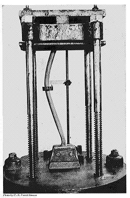
Figure 5
Testing a buggy spoke in endwise compression, illustrating the failure by sidewise bending of a long column fixed only at the lower end. Photo by U. S. Forest Service
The lateral bending of a column produces a combination of bending with compressive stress over the section, the compressive stress being maximum at the section of greatest deflection on the concave side. The convex surface is under tension, as in an ordinary beam test. (See Fig. 6.) If the same stick is braced in such a way that flexure is prevented, its supporting strength is increased enormously, since the compressive stress acts uniformly over the section, and failure is by crushing or splitting, as in small blocks. In all columns free to bend in any direction the deflection will be seen in the direction in which the column is least stiff. This sidewise bending can be overcome by making pillars and columns thicker in the middle than at the ends, and by bracing studding, props, and compression members of trusses. The strength of a column also depends to a considerable extent upon whether the ends are free to turn or are fixed.
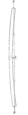
Figure 6
Unequal distribution of stress in a long column due to lateral bending.
The complexity of the computations depends upon the way in which the stress is applied and the manner in which the stick bends. Ordinarily where the length of the test specimen is not greater than four diameters and the ends are squarely faced (See Fig. 7.), the force acts uniformly over each square inch of area and the crushing strength is equal to the maximum load (P) divided by the area of the cross-section (A).
| ( | P | ) | ||
| C | = | --- | ||
| A |

Figure 7
Endwise compression of a short column.
It has been demonstrated4 that the ultimate strength in compression parallel to the grain is very nearly the same as the extreme fibre stress at the elastic limit in bending. (See Table 5.) In other words, the transverse strength of beams at elastic limit is practically equal to the compressive strength of the same material in short columns. It is accordingly possible to calculate the approximate breaking strength of beams from the compressive strength of short columns except when the wood is brittle. Since tests on endwise compression are simpler, easier to make, and less expensive than transverse bending tests, the importance of this relation is obvious, though it does not do away with the necessity of making beam tests.
[Footnote 4: See Circular No. 18, U.S. Division of Forestry: Progress in timber physics, pp. 13-18; also Bulletin 70, U.S. Forest Service: Effect of moisture on the strength and stiffness of wood, pp. 42, 89-90.]
| TABLE V | ||||||
|---|---|---|---|---|---|---|
| RELATION OF FIBRE STRESS AT ELASTIC LIMIT (r) IN BENDING TO THE CRUSHING STRENGTH (C) OF BLOCKS CUT THEREFROM, IN POUNDS PER SQUARE INCH | ||||||
| (Forest Service Bul. 70, p. 90) | ||||||
| LONGLEAF PINE | ||||||
| MOISTURE CONDITION | Soaked 50 per cent | Green 23 per cent | 14 per cent | 11.5 per cent | 9.5 per cent | Kiln-dry 6.2 per cent |
| Number of tests averaged | 5 | 5 | 5 | 5 | 4 | 5 |
| r in bending | 4,920 | 5,944 | 6,924 | 7,852 | 9,280 | 11,550 |
| C in compression | 4,668 | 5,100 | 6,466 | 7,466 | 8,985 | 10,910 |
| Per cent r is in excess of C | 5.5 | 16.5 | 7.1 | 5.2 | 3.3 | 5.9 |
| SPRUCE | ||||||
| MOISTURE CONDITION | Soaked 30 per cent | Green 30 per cent | 10 per cent | 8.1 per cent | Kiln-dry 3.9 per cent | |
| Number of tests averaged | 5 | 4 | 5 | 3 | 4 | |
| r in bending | 3,002 | 3,362 | 6,458 | 8,400 | 10,170 | |
| C in compression | 2,680 | 3,025 | 6,120 | 7,610 | 9,335 | |
| Per cent r is in excess of C | 12.0 | 11.1 | 5.5 | 10.4 | 9.0 |
When a short column is compressed until it breaks, the manner of failure depends partly upon the anatomical structure and partly upon the degree of humidity of the wood. The fibres (tracheids in conifers) act as hollow tubes bound closely together, and in giving way they either (1) buckle, or (2) bend.5
[Footnote 5: See Bulletin 70, op. cit., p. 129.]
Continue to:
My Books

