Model XII. A Newspaper Rack
Description
This section is from the book "Manual Instruction: Woodwork. The English Sloyd", by S. Barter. Also available from Amazon: Manual Instruction: Woodwork.
Model XII. A Newspaper Rack
Fig. 197
The construction of this model gives practice in planing, the half lap, and dovetail halving joint, corner chamfering, and bow sawing.
The whole of the orthographic projections should be made as in fig. 197, and if considered necessary in particular cases, the isometric projection can be made. In this latter, one arm of the model is omitted, in order not to confuse the eye by the number of lines. Bass-wood will be a very suitable material with which to make this model.
The base, which, when finished, is to be 5/8 in. thick, should be made of 3/4-in. wood 1 ft. 1 in. long and 6 1/2 ins. wide. The two cleats under the base forming the feet of the rack are to be made from a strip of wood 1 ft. 1 in. long and 1 in. square. For the sides and middle division of the rack, not less than 8 ft. 6 ins. of bass-wood will be required 1 in. wide by 1/2 in. thick, but it will be well to allow a few inches more for waste.
A strip of this length cannot conveniently be planed up. It should, therefore, be cut into three pieces, each long enough to make one of the upright pieces of framework. A strip 4 ft. 4 ins. long for the large middle division and handle, and for the two sides two strips, each 2 ft. 3 ins. long, will be large enough, and will allow for waste.
Plane all the wood true to dimensions, and cut up each of the thin strips into the required lengths for the parts. In marking the joints, and the length of the projecting pieces, as many as possible should be marked simultaneously, thus: take the four stiles (as the upright pieces are called) of the two similar sides, and arranging them so that all the face edges are in one plane, mark the length, and the size of the half lap and dovetail halving joints, in the manner shown in fig. 198, using square and chisel. The strips and the stock of the square can all be held together with the fingers. When marked, the lines showing the joints can be continued across the back of each piece separately, as shown in fig. 199.

End elevation.

Side elevation.

Isometric projection with one arm removed.
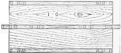
Plan.
Fig. 197.
The grooves for the half-lap joints, it must be observed, are cut in the back of the stiles, and in the face side of the rails, so that when finished, the face sides of all the pieces are together.
In marking the dovetail halving joint, allow the dovetail to be at least two-thirds of the thickness of the stile; and though this is not, strictly speaking, halving, the joint is often made in this proportion to obtain greater strength. These joints have to sustain the side against lateral strains, and, to obtain greater strength, they may even be dovetailed in the whole thickness of the stile. Figs. 200 and 201 show the two forms of joints.
The framework should be all jointed together, and the corners of the pieces chamfered, before being finally glued up and screwed to the base. The handle should be modelled with the spokeshave, as shown in the section on a b, fig. 197. After glueing up all the joints and cleaning off the surfaces, mortise out the slot in the middle of the ends of the base to receive the stiles of the large pieces of framing, and then cut and make the dovetail halving joint on the edges, and glue all the framework in its place.

Fig. 198.

Fig. 199.
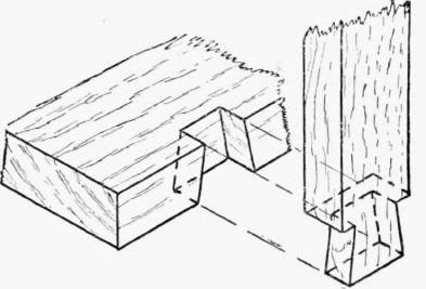
Fig. 200.

Fig. 201.
The supporting cleats for the base should now be planed up true, and the curve modelled with the spokeshave, chisel, and file. With l 1/4 -in. screws fasten the cleat to the bottom.
The screws which enter the bottom of the middle stiles should be put in first, and then those which enter the base in a sloping direction. The sides should be screwed in with 5/8-in. screws, preferably brass, and either flat or round headed, to give additional strength. The complete model can now be touched up with fine glass-paper on a cork rubber, but on no account touch the sharp corners of the chamfers, or they will certainly be injured.
Continue to:
My Books

