How To Make A Toy Cash Register
Description
This section is from the book "The Boy's Book Of Mechanical Models", by William Bushnell Stout. Also available from Amazon: The Boy's Book Of Mechanical Models.
How To Make A Toy Cash Register
AFTER you have finished making the toy scales, you probably will want a cash register to record the amount of the sale. It is not hard to make a model cash register, as shown in the drawing, planned of a size so that the drawer of the cash register is a cigar box.
The cigar box that you pick out for the drawer will be the basis of all your measurements, but when the toy is done, it will look like Figure I.
This is a toy which was made by a boy acquaintance of mine and which worked exceptionally well.
In appearance the cash register is as shown in Figure 1, but the details of the mechanism are shown in the other drawings. Figure 2 perhaps shows best how the toy cash register works.
There are six keys to this register, and these are made of ordinary pants buttons wired on to the end of a wooden lever L, cut of cigar-box wood. All of these levers are arranged in a row, pivoting on a wire W with about onefourth of the length outside the box part of the cash register. At the end of each lever inside is a tin piece T with a number on both faces. This tin is arranged below an opening in the wooden piece C, so that when the key b is pressed down, the other end of the lever goes up, and the tin piece T is exposed with its number, as shown in Figure I.

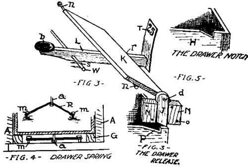
The drawer H slides in just under this row of levers, running on blocks G in the corners to hold it a little way above the floor of the register. Across the top of the row of levers inside the box is a flat piece of cigar-box wood K about two inches wide, or thereabouts, slanting as shown, and pivoted to end pieces A by the small nails n shown in Figure 3. You can see that whenever one of the levers is pressed it will lift up on the lower end of this piece K, causing it to turn around the nails n as a pivot.
At the right-hand end of the piece K, as shown at J in Figure 3, is a small wooden catch pivoted on a nail d, driven into the edge of K. This piece J is guided between blocks N nailed to the side pieces of the cash register case A. The catch J drops into a notch P in the edge of the drawer as shown in Figure 3. The lower part of the piece J is slanted, as shown, so that when the drawer is pushed into place, J is lifted and drops into the notch P, holding the drawer in place.
Figure 4 shows how a rubber band is arranged between small nails under the drawer to act as a spring and shove the drawer out whenever it is released. Two nails m are driven in the baseboard several inches apart while the nail a is driven into the bottom of the drawer. The nails m are toward the front of the case, while the nail a is at the back edge of the drawer. Thus, when the drawer is pushed in, the nail a catches on a rubber band stretched between the base nails m and pulls it back. When the drawer is clear in, the catch J holds it shut. A piece of wood V, Figure 2, as large as the front end of the case, is nailed to the front edge of the cigar box as shown, to keep the drawer from going too far in.
Now if you press one of the keys, you can see how the drawer will fly out, for when you press down on b in Figure 2, the lever I pushes up on K, no matter what button you may push. This lifts the catch J out from the notch P so that the rubber band is free to throw the drawer open, which it does. A little stop is nailed on the back of the slot piece E, Figure 6, so the drawer cannot fly too far out. This gives you the entire principle of a cash register, for the number plates T are numbered 1, 5, 10, 25, 50, and 100, and whenever you press the button opposite, this number is shown above, while at the same time the drawer flies open. By a little ingenuity you could arrange also to ring a bell by the action of K, if you wish.

Cash Register. Details of the Making.
Having explained the principle and also having shown the shapes of the pieces in the drawing, little else is necessary in describing how to make the toy cash register.
The end pieces A, Figure 1, are made from wood from a cracker box, as are also the shelf F in the first notch of the side pieces, the slot piece E in front of this notch, the strip C in the position shown at the top, and the piece D on the extreme top of the side pieces A.
Over the slanting part of the cash register frame is a tin piece X cut to fit and fastened in place with brads or small nails. Fasten this temporarily, however, as you will need to take this off to get at the mechanism if anything should go wrong.
With these directions, the rest will be easy.
Continue to:
My Books

