How To Make A Toy Phonograph
Description
This section is from the book "The Boy's Book Of Mechanical Models", by William Bushnell Stout. Also available from Amazon: The Boy's Book Of Mechanical Models.
How To Make A Toy Phonograph
HERE is a toy phonograph that will actually play real music, and you will also have the fun of making it yourself in your own workshop. You will have to buy the records and the needles, but all the other material you can pick up.
If you look at one of the hard rubber records, you will find that one spiral line is cut into the disk, starting at the center of the record and running to the outside. Examine this line closely, and you will see that it is not a straight but a wavy line. You may have to take a reading glass or a microscope to see the waves, but in most records you can see them quite plainly.
On the machine a needle follows this line as the plate turns, so that the needle moves back and forth, just as the record guides it. This wiggles the lever to which the needle N is fastened above, and that in turn causes the diaphragm h to vibrate.
When this thin membrane, called the diaphragm, shakes or vibrates, it makes the air vibrate just as the voice or the orchestra player that made the record did, so that from the diaphragm comes the sound of the voice or music sent out through the horn H.

Having this part explained, all the rest of the machine you need to understand is the part that turns the record or disk. That you can easily see from the drawings.
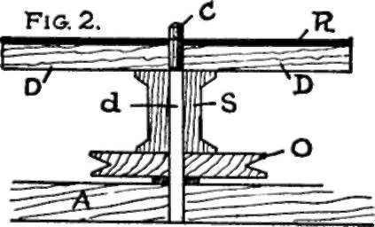
The record is shown at R supported on a wooden table or wheel disk D. This in turn is fastened to a spool S, which has at its bottom a pulley 0 fastened so that when this pulley turns, the record above is turned, all rotating about a stick or a shaft running up through the hole in the spool.
DISK AND PULLEY
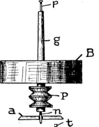
Off to one side is a flywheel B. You can probably find somewhere a small iron wheel and save the bother of making a wooden one.
This wheel is mounted on a shaft, as shown in Figure 4, having two pulleys - small ones - at its lower end, one of them level with the pulley 0 we have already fixed.
From the second pulley on this flywheel shaft a belt runs to a third and large drive pulley at X, Figure 1. This is arranged on the level of its pulley on g by putting washers under it between the base and the wheel.
The wheel 0 should have at least one washer under it to keep the wheel from rubbing on the baseboard when it turns.

On X a handle h is mounted. Thus, you see, when the handle is worked to turn X, this turns the flywheel at a high rate of speed. The belt from this turns 0, and thus the record is revolved.
In playing, when you make 0 turn ever so little faster, the music will jump up a key, and if you run it slower it drops down a key. The flywheel is to enable you to turn the disk at an even speed.
The wheels 0 and X are about three inches in diameter, and the heavier the better. The pulley on the shaft g below, shown at P in Figure 4, should not be more than three-quarters of an inch in diameter.
BALANCE WHEEL.
The shaft g is mounted in the frame F, f, Figure j, between bearings made of needles, Figure 4, the lower needle from the lower end of g passing through a hole in a small stick a, fastened to the base A, with its end resting and pivoting on a piece of tin or glass t. This is shown in the sketch of the "balance wheel."
How the disk and pulley are fixed is also shown in the separate sketch, Figure 2, and you can see in this the washer between 0 and A. The shaft d in this sketch is loose, so the spool S can turn freely about it. The short piece C above is tight and turns with D.
Now for the reproducer E, Figure 3. This is cut from a block of pine about two inches square on one end and two and a half or three inches long. Bore inch holes in this piece, as in the dotted line drawing, making one hole from the center of one end to within half an inch of the other, and then boring another to meet it at right angles, leaving a rim at least a quarter of an inch wide all around.
With a knife and wood-file trim and smooth this piece off until the hole is clean and smooth inside and the outside round. At the surface of the side hole fasten the diaphragm d as shown.
This diaphragm d may be a piece of thin writing paper, dampened and fastened on with glue. Or better, it may be a thin strip of mica or isinglass. Glue will fasten these too, and then glue a pasteboard washer a quarter of an inch wide on top of that, as at e.
The lever I is shaped, as shown, from a piece of hardwood and fastened to pivot loosely on a wire or brad X, in a wooden crotch K, glued to the side of the reproducer in the position shown.
For the points buy a paper of loud victrola needles. The length from the tip of the needle to the center of the diaphragm, - the other end of the lever, - is about twice the length from the center of the diaphragm to the wire X. That is, the wire X should be midway between the needle end and the diaphragm center. I once made a talking machine with a reproducer six inches in diameter, using a piece of tin tacked on the side for the diaphragm, and a pine lever. It worked as well as any other I have tried, but was too big and cumbersome.
A bit of candle wax or glue will fasten the lever end to the center of the diaphragm. The needle N fits into a tiny hole in the lever end made with a brad driven in and pulled out again, and is held in place by a tiny screw at the side, procured from some jeweler's scrap heap.
If the paper diaphragm is put on dampened, when it is dry you will find it as tight as a drumhead. The horn may be of tin or pasteboard, funnel-shaped of course, and fitted into E at its small end. You can easily figure out the pattern by making one of a newspaper or a bit of wrapping paper first, and then copying it with the material you want to use.
The horn is held in place by a wire holder W bent into a loop at one end for the screw to go through to hold it to the base, and into a sort of "Y" at the upper end as at V for the horn to rest on.
The base can be made of a cigar box, which provides an admirable sounding-board.
Continue to:
My Books

