Detachable Parts Of The Universal Metal Cutter
Description
This section is from the book "Workshop Receipts For Manufacturers And Scientific Amateurs. Supplement Aluminium To Wireless", by The Chemical Publishing Co.. Also available from Amazon: Workshop Receipts For Manufacturers And Scientific Amateurs.
Detachable Parts Of The Universal Metal Cutter
It is important that the detachable parts should be clearly understood. They are in the first instance the outer and inner nozzles D and C. These (more especially the former) require occasional renewal. The spade guide A (Fig. 49) is also liable to require renewal.
When repairs or renewals, other than the nozzles D and C and the guide A are required, the blowpipe should be returned to the makers in order to have these effected. Where this is not possible the valves and motion parts assembled in the body f can be obtained separately and renewed by any competent mechanic. In order to effect such renewals the shank of the blowpipe can be detached from the body by first unscrewing as far as possible the back nut 2 on the pipe w and the back nut 3 of the screwed connector 4 which holds the junction-piece v in position. The connector can then be screwed back on the pipe w until it clears the socket projection of the body, when the two main portions of the blowpipe can be separated by withdrawing the junction-piece v from the body. Under no circumstances must any attempt be made to disconnect the pipe to reassemble, a new jointing disc will probably be required between the body and the junction-piece v. These discs are supplied by the Company and the joint must be carefully made, for if there is any leakage of oxygen into the combustible gas passage back-firing and heating of the shank will occur. Grummet joints must also be made in tightening up the back nuts 2 and 3 in order to prevent any leakage of combustible gas outwards.
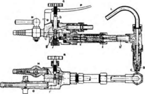
Fig. 50.
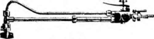
Fig. 51.
(b) The " S " Type Metal Cutter is illustrated by Fig. 50. The following description applies also to the cast iron cutter (Fig. 51). It will be seen that there are no enclosed tubes on this cutter, and that everything possible has been done to enable it to be easily and quickly dismantled by anyone, and damaged parts replaced without loss of time. The working principles are identical with those of the " Universal" cutter just described ; we will, therefore, merely indicate the difference in structural details : The supply of combustible gas and oxygen is taken through the body piece exactly as in the " Universal " cutter, the heating oxygen passing from the valve R along the pipe s to the injector a, the combustible gas being drawn along the outside of the pipe s, and discharged mixed with the oxygen, by way of the expansion head b 1 through the annular heating nozzle D.
The cutting oxygen passes from the valve b, the action of which! has been already described, through; the pipe I to the central cutting' nozzle C
Inner and outer nozzles and guides are interchangeable between " S " type and " Universal " cutters.
Continue to:
My Books

