The Endurance Pressure Regulator
Description
This section is from the book "Workshop Receipts For Manufacturers And Scientific Amateurs. Supplement Aluminium To Wireless", by The Chemical Publishing Co.. Also available from Amazon: Workshop Receipts For Manufacturers And Scientific Amateurs.
The Endurance Pressure Regulator
A pressure regulator must be fitted to all oxygen cylinders employed for metal cutting.
Endurance regulators are manufactured by the Company in large quantities and are specially designed for yard and workshop use. They are positive in action and possess none of the multiple link movements usually employed in articles of this description, the high and varying pressure of oxygen in the cylinder being automatically reduced to any constant low pressure desired for the work in hand. They are fitted with a gas expansion device and special valve seat which obviates ignition risks ; the movement of the regulating diaphragm is small and consequently it will last for many years without renewal.
The regulator (Fig. 52) is attached to the cylinder by means of the flynut and nipple F, the high pressure gauge H registering the contents of the cylinder.
The outlet pressure is regulated by means of the crutch screw .1, the pressure thus obtained being recorded by the low pressure gauge O is the outlet valve and C the connection to which the tubing from the cutter is connected. The safety valve S prevents any dangerous pressure being reached in the regulator body ; it also acts as a safeguard for the low pressure gauge.

Fig. 52.
The regulator should never be dismantled by the user. If it becomes defective in operation it should be returned for overhauling.
The Hydraulic Back Pressure Valve-With all oxy - acetylene cutting blowpipes where acetylene is drawn direct from a generator, or from an intermediate acetylene gasholder, a hydraulic valve is a necessity. It must be fixed on the acetylene supply pipe in a vertical position and as near to the cutting blowpipe as convenient. In the case of fixed generators a good position for the hydraulic valve is on a wall, and the bottom should be about four feet from the ground. The acetylene inlet pipe coupled to the tap A should extend vertically not less than three feet above the tap.
In cases where two or more metal cutting blowpipes are worked from the same acetylene supply, a separate hydraulic valve must be employed for each. Where portable generators are employed the hydraulic valve is fixed to the generator (D, Fig. 53). All hydraulic back pressure valves are, however, similar in the essential features of construction and operate in the same way. When it is kept charged with water the hydraulic valve precludes the possibility of oxygen at any time flowing back along the acetylene supply pipe. Referring to Fig. 53 its action is as follows :-

Fig. 53.
The acetylene pipe from the gasholder or generator is connected to the tap A, and the acetylene tube leading to the blowpipe is connected to the tap B. C is a cup with a loosely-fitting lid into which water is poured to charge the chamber D up to the level of tap E. The tap A must be closed whilst the chamber D is being charged with water. When water shows at the tap E immediately stop filling, and after allowing time for surplus water to drain off, close tap E. The lid must then be replaced on cup C and the tap at A may be opened.
The valve is then in working order. The filling pipe F is made long enough to hold a column of water greater than the pressure of the acetylene, which should not be less than 8 inches of water. When at work the taps A and B must be open and the supply of acetylene regulated by the tap H on the cutting blowpipe (Figs. 49 and 50). Should the nozzle at any time be-come choked whilst the oxygen supply remains unchecked, this gas would be forced by its superior pressure along the acetylene pipe. The back pressure thus caused, acting on the surface of the water in the chamber D, would force the water up the pipe F, displacing the lid on cup C. The hydraulic seal would thus be destroyed, and both gases would escape into the atmosphere until the taps A and B were closed, thus oxygen can never penetrate the acetylene supply pipe beyond the hydraulic valve provided the hydraulic valve is properly filled with water.
For cutting cast iron 8 large size hydraulic back pressure valve should be employed, or two standard size valves may be coupled together with a " Y " piece, otherwise, the rapid passage of the acetylene is liable to displace the water.
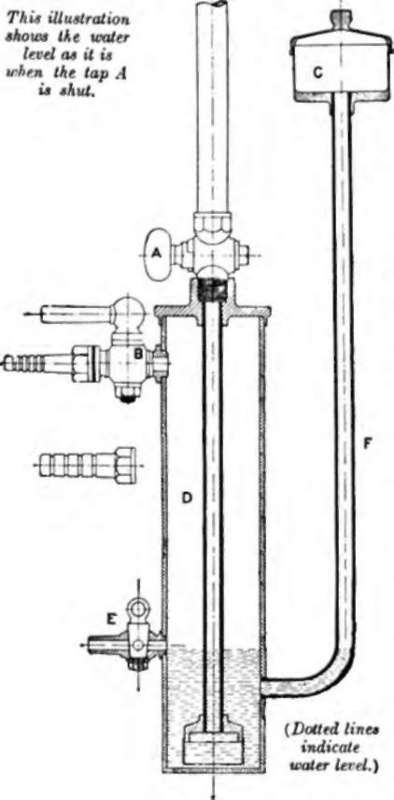
Fig. 54.
Further notes on the working of the hydraulic valve are given later.
Continue to:
My Books

