


Lathes
Description
This section is from the book "Workshop Receipts For Manufacturers And Scientific Amateurs. Supplement Aluminium To Wireless", by The Chemical Publishing Co.. Also available from Amazon: Workshop Receipts For Manufacturers And Scientific Amateurs.
Lathes
The principle of the working of all modern lathes is the same, from the small treadle lathe to the largest, having its own electric motor of many horse power. The modern lathe is also with its separate attachments capable of many other operations than that of simply turning, and stiff in itself, and therefore needs no outside support whatever. This cantilever design is unique in that it enables the lathe to be bolted down on any floor, no matter how uneven, without distorting or affecting its accuracy in any way ; it is the only form by which a small lathe can be made or guaranteed to remain accurate wherever placed.
The bed is a complete box section casting, stiffened internally,

Fig. 89.
Fig. 89 shows one of the best known makes of treadle lathes, i.e., the 3 1/2 in. made by Messrs. Drum-mond Bros., Ltd., and the following details of its construction may be safely taken as including the best design for the purpose.
The bed has a longitudinal form that is completely self-contained and is of the same general design as our new toolroom and manufacturing lathe beds. Although the top surface of the bed is flat, it is not the ordinary so-called " flat English bed." The Drummond form of lathe bed combines the accuracy of the long narrow guides of the " American " type with the long wearing qualities consequent on the large wearing surfaces of the " English " type.
The design gives a 90° vee saddle guide at the front of the bed, the centre line of which coincides approximately with the average line of cutting thrust. The vertical downward component of this thrust is taken on the top surface of the front way, the horizontal forward component of the cutting thrust is met squarely by the back face of this way. The rear way is separated from the saddle by clearance, and the saddle is firmly held to the top face of this way by the stiff gib shown. Thus the cut itself holds the saddle to a long narrow guide at the front of the bed.
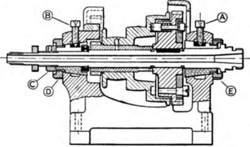
Fig. 90.
The leadscrew is brought close in under this saddle guide, thus reducing to a minimum the unavoidable " wringing " action between these elements, and ensuring a clean, steady saddle movement.
The Headstock
This is positively and permanently clamped against the flat vertical face of the front way of the bed, thus ensuring alignment of the spindle with the ways. In earlier designs an overhead arm joined the two main bearing bosses of the headstock casting, but the modern design is provided with a heavy cast beam on base, which ensures absolute rigidity and great strength with fully adequate support for the spindle bearings.
The hollow spindle is fitted with ball thrusts (see Fig. 90) and runs in hard phosphor bronze bearings, which are adjustable by contraction into their coned seatings in the headstock casting. These bearings are exceptionally long and are spaced widely apart.
A special spindle and cone pulley lock is provided. To disengage the cone pulley from the gear keyed to the spindle, so that the back gears may be used, the knurled knob on the front face of the gear is pushed away from the operator ; this automatically withdraws the locking pin by means of a cam slant cut in the face of the plate gear ; to re-engage for direct drive the knob is pulled towards the operator, when a spring action automatically returns the locking pin. This lock has thus the simplest motion possible, requiring the least time and trouble in its operation ; no nuts, screws, spanners or pull-out pins are employed, and in the somewhat restricted space available it forms a very accessible and convenient arrangement. Just a push of the knob, forwards or backwards, and the cone is freed or locked.
The back gears work on an eccentric bearing spindle, and cast iron gear guards are fitted. The whole headstock is of massive design and of great length for the size of lathe.
The mandrel nose is provided with a square ground shoulder as register behind the thread ; this ensures perfect running truth of faceplate or chuck.
Method of Adjustment of Bearings
(See Fig. 90).-The method of adjustment of the main bearings will show just how these are constructed. First slack off thrust nut C. Front : (a) Slack bearing locking screw A. This allows bearing to be contracted, (b) Adjust bearing by screwing down bearing nut E. This contracts bearing by pulling into taper housing, (c) Lock bearing by screwing down locking screw A. Back : (d) Slack bearing locking screw B. (e) Adjust bearing by screwing up bearing nut D. (f) Lock bearing by screwing down locking screw B. Readjust thrust nut C.
The tailstock is a stiff box casting, with steel barrel and square thread screw, and for turning long tapers it has a set-over adjustment, which may be set by means of a zero graduation.
It is guided in similar manner to the saddle. A single action of the lever at its back rigidly locks the tailstock to both the front and rear ways by means of adjustable eccentrics. This is done without putting any distorting or squeezing strains upon the bed, and gives a very large weight taking and wear resisting area. Note that the alignment of the tailstock is obtained by locking to the same vertical face of the ways as the headstock, and that this face also guides the saddle.
The Special Toolholder with Height Adjustment (Norman's Patent).-This toolholder has been evolved as the result of continuous experiments and many years of experience in the design of various types, and we think we can now confidently claim to have produced what has hitherto been lacking-a perfect toolholder for small lathes.
Continue to:


My Books

