Lathes. Part 2
Description
This section is from the book "Workshop Receipts For Manufacturers And Scientific Amateurs. Supplement Aluminium To Wireless", by The Chemical Publishing Co.. Also available from Amazon: Workshop Receipts For Manufacturers And Scientific Amateurs.
Lathes. Part 2
A Comparison With Other Types
In considering the advantages of the new holder over other types the following points should be noted.
Firstly, there is the question of the manner in which the tool is clamped to the topslide, and on this depends to a great extent the rigidity and accuracy of the latter, as well as the freedom from chatter, etc., of the tool. The single-clamp bolt with tool block and double set-screws, gives an excellent holder, providing care is taken in securing the block on the topslide before the tool itself is screwed in position. The four bolt and double clamp plate method is exceedingly cumbersome, and in both these methods the stresses due to clamping the tool are imposed on the topslide itself with a tendency to impair the accuracy of the latter. In the case of the American holder this means a weakening of the topslide caused by the necessary base slot.
Secondly, there must be some means of adjusting the height of the tool; this is usually done by packing or by the provision of a holder of the American type. Packing the tool is not an ideal method, and in the case of the American holder with its arc-shaped packing wedge-although this gives a fairly simple tool setting in one respect -it alters the cutting angles of the tool with each adjustment for height.
Thirdly, there is the question of convenient holding of boring bars and tools, and all these methods are subject to limitations in respect of their ease of tool setting.
All these points are successfully dealt with in the new design tool-holder. ' It will be seen that the toolholder itself is clamped to the cylindrical post or pillar which is cast integral with the topslide, and thus all clamping stresses are confined to the toolholder itself. Only the normal cutting stresses are carried by the topslide, which in itself has additional strength owing to the extra metal just in the right place which the post gives.
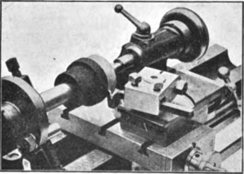
Fig. 91.
The toolholder itself consists of a hardened steel block cut from the solid with a central hole a sliding fit on the topslide pillar. The block is split so that it may be clamped to the pillar by means of a hardened clamping bolt. The tool itself is carried in a square hole through the toolholder, and is held by means of two hardened set-screws. It will be seen from the two illustrations reproduced herewith that this tool-holder is quickly adaptable to turning or boring operations, and it has a complete range of movement round its pillar.
Perhaps the greatest feature, however, of the new toolholder is that it provides for height adjustment of the tool relative to the lathe centres. A range of movement of about fin. is provided, the tool being clamped firmly in its square hole all the while, and one quick movement of the spanner on the clamping bolt being the only action required for locking the holder in any position.
It should be noted that the cutting rake and clearance of the tool remain constant for all height settings, as of course the tool is shifted bodily up or down, and does not change its angle with relation to the slides.
Fig. 91 shows the lathe set for plain turning. It will be noticed how simple the tool setting is and how the provision for height adjustment simplifies this operation.
Tools made of different sections of tool steel are accommodated to bring their cutting edges to the correct height and in setting tools for side cutting, facing or taper turning, the correct position may be obtained immediately, and the single clamp grips the holder tightly in a second.
The Leadscrew is cut on a special machine fitted with pitch correcting gear; its rear end bearing is bronze bushed, and at its headstock end a clutch is fitted for both hand and automatic throwout, which can be set to operate at any position of the saddle along the bed to prevent overrunning.
The Saddle is provided with rack and pinion traverse motion operated by handwheel, and a split-nut device for disengaging the lead-screw is operated by means of the knob on the left of the apron. The slide-rest is fully compound, and the cross-slide is formed as a large T-slotted boring table. The cross-slide screw is fitted with micrometer index. The Topslide is fitted with a graduated base ; its leadscrew is brought to the side of the vees, thus enabling the use of a much longer nut than formerly, and giving longer life and protection from chips, etc. Both slides have unusually long bearings, giving great accuracy and firmness in operation.
The set of Change Wheels supplied as standard is as follows :- Two 20, two 30, one each 35, 38, 40, 45, 46, 50, 55, 60, 65, 73. All gears are machine cut from the solid blanks, and the set covers Whit-worth threads from 40 to 8 threads per inch, metric from 0-5 m/m. to 5 m/m. pitch, and a wide range of other threads and feeds. The screwcutting change gear studs are fitted with a patented spring plug retainer ; to remove change wheels the plug is merely pulled out by its head, when the wheels can be instantly changed without bother with nuts. The change gear quadrant is provided with a second quadrant to the rear for the clamping nut.
The treadle lathe Flywheel and the head of the pitman link run on large ball-bearings ; the flywheel is balanced and of great weight for the size of the lathe. All slides are hand scraped to surface plate. 1
In addition to a lathe being wel designed it is essential for good work that it be accurately made, and able to pass easily the following tests : These are simple tests such as could be applied in any workshop without special apparatus. Remember that the cutting of a test piece in a lathe is not a proper test, since the results depend on a dozen things which may affect the result-tool wear, hardness of material, etc., and to no small degree on the mechanic himself. The tests described may be relied upon to show the true state of the machine, and are arranged in a proper sequence so that the value of the test does not depend on the accuracy of some other part of the machine being assumed. In all cases the test may be made in less time than it takes to tell about it.
Continue to:
My Books

