


Lathes. Part 3
Description
This section is from the book "Workshop Receipts For Manufacturers And Scientific Amateurs. Supplement Aluminium To Wireless", by The Chemical Publishing Co.. Also available from Amazon: Workshop Receipts For Manufacturers And Scientific Amateurs.
Lathes. Part 3
Test No. 1. Testing the line-ability of the centres. A long bar is mounted between centres ; this should preferably have two portions near the ends accurately ground, but this is not essential, as the bar may be reversed end to end and the test made on the same portion of the bar at each end of the lathe. A micrometer head is mounted in any simple holder in the tool post, first in a horizontal position, as in Fig. 92. Readings are taken at the headstock and tailstock ends of the machine, reversing the bar if this is not precision ground. This indicates the error in alignment, if any, of the centres with the ways of the bed. As a second part of the same test, the micrometer head should be mounted in a vertical position in the tool post so that the anvil may be brought to read downwards on the bar. End to end readings are then taken, and these will indicate the error in height of centres.
Before proceeding with further tests the errors found in the pro-ceding tests should be corrected temporarily by packing or setting over the tailstock ; scraping should not be carried out until the whole machine has been examined, as the errors may be due to lack of alignment of the headstock, etc. When the readings for the above tests are satisfactory, further tests may be applied with certainty.

Fig. 92.
Test No. 2. Testing the line-ability of the tailstock. This is an extension of the first test, and is carried out with the same apparatus. By taking readings on the tailstock pnd of the bar with the tailstock barrel first in, then protruding, with the micrometer head in horizontal and vertical positions, any error in lineability of the tailstock is at once determined.
Test No. 3. Testing the line-ability of the headstock. For this test the micrometer head is mounted, as in Fig. 93 on a cross bar, which is carried on a long bar between centres, so that the anvil may be brought to bear on any point on a large faceplate. The micrometer should be read when at the top and bottom of the faceplate in a vertical direction, and again at the front and rear in a horizontal direction. In making this test the micrometer should always be applied to the same spot on the faceplate, which should be rotated accordingly in unison with the cross-bar. This method precludes the possibility of any error of the faceplate affecting the test.
The vertical readings will, of course, show any error in the alignment of the headstock in a horizontal direction, and the side readings will indicate the alignment of the headstock with the ways of the lathe.
Test No. 4. The squareness of cross slide with the bed. A micrometer is placed in the tool post as in Fig. 94, facing the faceplate. Readings are then taken, first with the tool post at the near side of the faceplate, then with it in the far position, the plate being revolved for this so that the same spot is measured ; this again eliminates any error in the faceplate itself. If any error in the alignment of the headstock was found in Test No. 3, this must be allowed for in this test, and any remaining error will be due to lack of squareness of the cross slide.
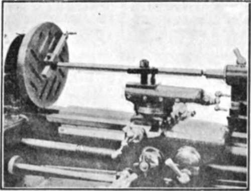
Fig. 93.

Fig. 94.
This series of simple tests gives all the information required as to the actual condition of the lathe in a definite form.
We now illustrate the method of testing another important item, the pitch of the leadscrew. In cases where accurate screwcutting is to form part of the duties of the lathe, the leadscrew must be accurate both as regards pitch and periodic aberration. The periodic errors are determined by means of a special rig, the lathe carriage being pulled towards the tailstock end of the lathe by means of a weight and pulley arrangement, and the end of the leadscrew being checked by means of a dial indicator held in a special fixture. A method of checking the pitch of the leadscrew used in our works is illustrated in Fig. 95, and this is capable of showing extraordinarily small deviations from the truth. It will be seen that the pitch of the leadscrew is tested in the working position by comparison with the Society Gene-voise Rule, with the aid of a microscope ; the rule is carried on two brackets, and the microscope is focussed upon the lines (invisible to the naked eye) on the optical rule. On making a number of turns of the leadscrew, the mark is again noted in the microscope field, and any error in pitch is shown directly. A special wheel and stop is provided to ensure that the indexing of the screw is perfectly true. Errors of one ten-thousandth of an inch are quite obvious by means of the microscope, and it will be apparent that this method gives the errors of the leadscrew in a very direct manner, the leadscrew being under actual working conditions meanwhile.
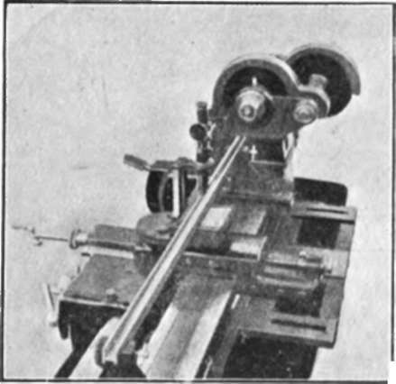
Fig. 95.
The following notes on Tool Angles, etc., by Messrs. Drum-mond Bros., Ltd., will be of interest :-
Continue to:


My Books

