Timken Bearings For Motor Cycle Hubs
Description
This section is from the book "Workshop Receipts For Manufacturers And Scientific Amateurs. Supplement Aluminium To Wireless", by The Chemical Publishing Co.. Also available from Amazon: Workshop Receipts For Manufacturers And Scientific Amateurs.
Timken Bearings For Motor Cycle Hubs
With fixed spindle designs, either plain or screwed bore cones can be employed, as is illustrated in Fig. 14. The adjustable cone should, wherever possible, be located at the near-side end of the hub, as this permits of the use of a right-hand screwing. Where, however, adjustment is arranged at the off-side end, left-hand screwing must be employed.

Fig. 14.
In the design illustrated, plain bore cones are used. In this case the right-hand nut is screwed hard up to the shoulder of the spindle, whilst the dust-excluding cover, having a tongue or key engaging with a slot or key-way in the spindle, acts also as a security washer.
Adjusting Device for Timken Roller Bearings (Fig. 15).-In order to obtain full benefit from Timken roller-bearings, an efficient and convenient means should be provided for their adjustment. The device shown is particularly applicable for commercial vehicle axles or other designs in which the bearings are mounted near the end of the spindle. The two threaded nuts, with kev washer between, form a combination in which the inner nut is positively locked against rotation, while the outer nut clamps the parts solidly together. By offsetting the tongue, or flat, in the key washer one quarter of the hole spacing, an increment of adjustment of one-half the hole space is possible by reversing the key washer. The cotter at the end, or a soft metal washer interposed between key washer and outer nut, eliminates all possible chance of the outer nut working off, permitting of the key washer coming out of engagement with pin in inner nut.

Fig. 15.
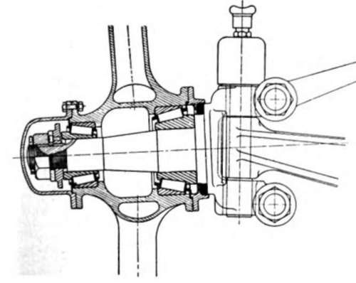
Fig. 16.
Adjustment of front wheels is best accomplished by drawing up the adjusting nut reasonably tight, and at the same time rotating the wheel several times. The object of this is to ensure that all component parts of the bearing are properly seated, the cones and cups seating firmly against the shoulders on the spindle and on the interior of the hub. After having drawn the adjusting nut up slightly, it should be backed off one-third or one-half turn to a point where the wheel is free running, but not sufficient to permit of more than just the least perceptible shake in the bearings. The adjusting nut should be locked in the final position, see Fig. 16.
The amount of the turning back is influenced directly by the coarseness of the thread. General practice is to use a comparatively fine thread, usually sixteen threads to the inch. This thread has the advantage of being fine enough for the purpose, and yet coarse enough to be an economical manufacturing proposition, and of suitable proportions to withstand vibration. A finer thread, namely, twenty to twenty-four to the inch, while permitting of finer adjustment, does not stand up so well under vibration.
Continue to:
My Books

