Work Between Centres
Description
This section is from the book "Workshop Receipts For Manufacturers And Scientific Amateurs. Supplement Aluminium To Wireless", by The Chemical Publishing Co.. Also available from Amazon: Workshop Receipts For Manufacturers And Scientific Amateurs.
Work Between Centres
Care is required here in order to avoid undue wear on the centre in the back or tailstock. The recess in the work for the centres should be to the correct angle, and should never allow the actual point of the lathe centre to bear on the work. The hole or punched recess in the work should be drilled or punched with a tool having a 90 degree cutting or punching end as the case may be, after which a small drill, say -1/16in. diameter or larger, if the work permits, should be run in at least a distance equal to its diameter; this will prevent the centre point from becoming worn or damaged, and will throw the pressure of the work on to a place on the centre where it is better able to stand it. Plenty of oil should always be used on the centre when turning, and the centre must be kept well up to its work.
Drilling
A ready means for this operation is given by the ease in which a drill can be held by a self-centring chuck, and the work brought up to it by the back centre, also by the fact that a drill with a Morse Taper shank will hold in either the mandrel end, or in the tailstock, due care being taken that the correct size taper is used to fit the lathe, and that no chips, etc., are present when the drill is introduced, also that the drill shank is in perfect condition, i.e., not surface damaged in any way. Fig. 104 shows a complete Milling and Gear-Cutting Attachment in position on a lathe by means of which any operation ordinarily required can be carried out, and of which a specification would be as follows :
Dividing Head
Stiff headstock bracket carries steel worm in long bearing with eccentric sleeve to allow for taking in and out of mesh with the mandrel plate gear, and for adjusting for backlash ; changeable dividing plate, dividing sectors, crank and spring plunger.
Milling Head
Mounted on lathe topslide, has universal movement. Vertical slide has steel screw, hand-wheel and micrometer index. Hollow cutter spindle has taper bore and nose for standard bore cutters both ends, and is reversible end to end to allow for working close up to faceplate or tailstock. Spindle housing can be rotated through complete circle, and is graduated in degrees. Spindle is driven by steel and phosphor bronze spirals, fitted with ball thrusts, from vee-grooved pulley for round belt.
Cutter Drive
Treadle or self-contained motor driven lathe : Flat belt from flywheel to pulley on attachment overhead countershaft. From three - step vee-grooved sliding pulley on this splined shaft to cutter head, by round belt over traversing counter-weighted jockey pulleys. Power driven lathe : By flat belt from extra pulley on lathe countershaft to flat pulley on attachment countershaft, thence as above.
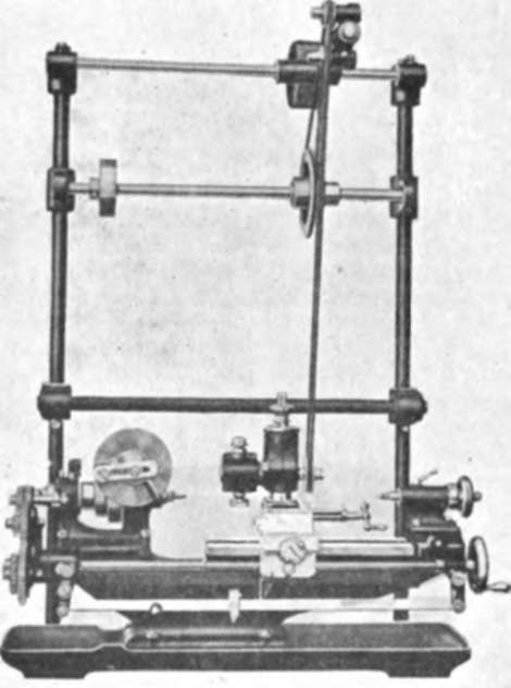
Fig. 104.
Attachment Overhead Bracket
Of very heavy section steel tubing, with massive cast iron sockets and elbows. Perfectly rigid under the heaviest cut.
Range Of Work
Spur and bevel gears, worms and worm wheels, spline and flute cutting, squaring ends of shafts, etc., plain end-milling with work on faceplate or angle bracket, etc.
For work that in the ordinary way is too big to swing in the lathe, the headstock can be packed up to t he required amount, and bolted firmly down with longer bolts. The amount of work that can be done and the different operation carried out on even a 31/2 in. lathe is remarkable, and as an example of such work, with the different operation, the following may be given of machining a piston for an internal combustion engine to the best advantage. The operations described will serve as a typical example of the manner in which a piece of work should be tackled, following a logical sequence of settings.
Chuck open end of piston ; rough turn the spigot ; rough face the end. (Note :-This is necessary to allow a good grip for chuck jaws, and to prevent distortion of piston.)
Grip piston by spigot. Turn over the top, and face end. Turn grooves for rings. Bore through bosses to size. (Note ;-This ensures that the final facing operation will leave the bosses even in relation to the centre of the piston.) Before removing from chuck, scribe a line with a fine pointed tool round the piston. This will give the exact location of the gudgeon pin.
Remove from chuck and cut spigot off with hacksaw.
Clamp a block of wood in the chuck and bore out to a good fit for the piston. Insert the piston and face the end.
Line up piston to scribed lines, and clamp in piston. Drill the pin holes, leaving enough metal to finish with a single pointed boring tool. Finish bore the pin holes with boring tool set in boring bar running between centres. Face the bosses with facing cutter also set in boring bar.
We are indebted to Messrs. Drummond Bros., Ltd., for the following notes on the Working and Hardening of Cast Steel or Tool Steel :-
Preliminary
Tool steel, cast steel or carbon steel should be softened or annealed before any attempt is made to work it into shape. This can be effected by heating to a cherry-red heat (750° C), after which the steel is covered up in dry sand, lime or fine ashes, and left until cold.
Forging
Careful heating is very important, and should be done slowly, and evenly throughout ; then bring up to the proper temperature as rapidly as possible.
Generally speaking, tool steels should not be heated over bright red heat (800° C), but no hard and fast rule can be laid down. Great care must be taken in this respect, as when once the steel has become overheated it becomes useless. Always keep the heat as low as possible, to admit of the necessary forging being done, but not lower than a cherry red (750° C). After forging, reheat to a cherry-red heat, and allow to cool as in the previous annealing, by covering up in dry ashes.
N.B.-This relieves the internal strains set up during forging.
Continue to:
My Books

