Cranks And Treadles Of Foot Lathes. Continued
Description
This section is from the book "Turning And Mechanical Manipulation", by Charles Holtzapffel. Also available from Amazon: Turning and Mechanical Manipulation.
Cranks And Treadles Of Foot Lathes. Continued
Fig. 43.
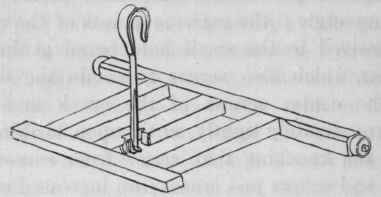
When the lathe is at rest, the bend of the crank hangs downwards and the length of the hook should then permit the footboard of the treadle to hang just clear of the floor. In starting the lathe into motion, the foot is placed on the treadle, the driving band is taken between the finger and thumb of the left hand, just below the mandrel pulley, and pulled downwards; this causes a semi-rotation of the fly wheel, turning the bend of the crank upwards, and then as the latter passes the perpendicular, the pressure from the foot is first applied to the treadle; upon which the wheel at once takes up and continues the motion.
To avoid the necessity of starting the lathe in this manner; it is frequently recommended that the fly wheel should be sufficiently weighted at one part of its circumference, to overbalance the weight of the treadle, that when the lathe is at rest, the bend of the crank may stand nearly horizontally instead of hanging vertically. The footboard of the treadle then hangs a few inches off the floor, and the lathe will start into motion immediately the foot is placed on the treadle, without its being requisite to touch the band.
This practice is to be deprecated; as the unequal disposition of the weight upon the wheel, is most injurious to its momentum. The fly wheel can no longer convert the unequal forces applied through the crank into perfect uniformity of motion, but compelled by the weight that has destroyed its balance, it may be said to register every separate revolution; the vibration introduced by the weight, being distinctly felt in every revolution of the lathe and seen marked in the varying quality of the surfaces turned upon the work. Besides the foregoing objection, the counterpoised wheel is a disadvantage for delicate or precise work, and the lathe to which it is applied always shows a disinclination to stand perfectly still; necessary for the adjustment, measurement or fitting, constantly required for ordinary small works in wood or metal. The lathe can be made to rest quiescent, provided the weight be in excess, but that only increases the former evil, and even then a slight accidental touch on the treadle will set up some motion. When long and heavy treadles are employed, there is some advantage in their weight being partially balanced; but the counterpoise should be applied to the treadle itself, when it can in no way interfere with the momentum of the wheel. In the slide lathe fig. 114, the back of the treadle is sufficiently extended beyond the centers upon which it works, to partially neutralize the weight of the front.
An exceptional form of treadle carrying the hook or link horizontally fig. 44, has been tried. The hook is jointed to the end of a strong bracket affixed upright on the treadle, and terminates in a sort of curved finger which rests against one side and on the top of the neck of the crank. The action is nearly the reverse of that of the ordinary hook, the crank being pushed forward instead of being pulled downward. Mr. Lukins, the inventor, thus described the advantages he claimed for it: "A crank with a short connecting rod, turns one of its dead points much more quickly than the other; advantage is taken of that peculiarity in the arrangement of the crank in this lathe. The slow turn takes place at the bottom of the tread, and the too quick return upon the foot which occurs in the common mode is consequently avoided."
Fig. 44.

Fig. 45.
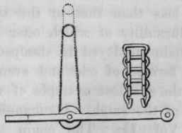
Fig. 46.
When tried practically, this treadle proved far less smooth and agreeable in its action than the old form; the quick return is transferred to the top of the circuit, whence it gives a jerk and vibration to the knee and body not experienced with the ordinary hook, which appears to have been altered but not improved. Another treadle has been recommended, on the score of the footboard being hinged, so that it may yield in the event of the foot being accidentally placed beneath it; the treadle is weakened and the alteration appears hardly necessary.
In the late Mr. Clement's treadle fig. 45, the crank has a wide flat neck, or carries a small pulley, and the pin on the treadle is replaced by a larger pulley, the hook being exchanged for an endless chain. The chain rolls around the neck of the crank and the treadle pulley, and was considered by Mr. Clement to produce less friction than the hook; this arrangement is sometimes adopted. There is a smooth and agreeable action in the chain, but its elasticity and stretching under the pressure of ordinary work, greatly detract from its apparent advantages ; the friction of the numerous pins as the chain bends around both the crank and the pulley, is also but little less than that of the steel crank hook, the rigidity and durability of which offer great recommendations. The flat chain employed is stamped from sheet metal, the links being formed of odd and even numbers of plates joined by pins, the smallest example of which is found in the winding chain of the watch. Its manufacture is described pages 939, 940, Vol. II. The chain known as Vaucanson's chain fig. 46, each link formed of round wire and capable of detachment, so as to vary and adjust the total length, is also conveniently used as a driving chain, for this and many other purposes.
Continue to:
My Books

