Mechanism Of An Organ
Description
This section is from the book "The Corner Cupboard; Or, Facts For Everybody", by Robert Kemp Philp. Also available from Amazon: The Corner Cupboard; or Facts for Everybody.
Mechanism Of An Organ
Organ (Mechanism Of An). Since the bellows are of so much consequence, we will begin by explaining their construction. They are what is termed double bellows, consisting of two moveable parts and keeping up a continual blast. Fig. 1 shows them in section as they appear when full of wind.
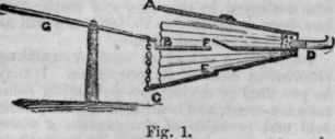
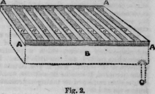
They consist of three boards, A, B, C, united by leather as in a common pair used in a house. The two lower boards have a hole in them, covered by a valve of leather, opening upwards. The upper board is weighted, the middle one being fixed, and the lowest capable of moving up and down by the handle G. In the diagram, the valves are shown in the position which they take just as the lowest board begins to be raised by the handle; the air contained in the lower part will close E, and open F, through which it enters the upper compartment: Thus, all the air will pass upwards, till the board C reaches its highest position; then, on letting go the handle G, C will fall by its weight, more air will enter from without by E, and that contained in the upper part, closing F, is driven through D into the organ by the falling of the upper board : thus, if C is again raised before the air in this upper chamber is exhausted, a constant blast will be kept up. (Whenever double bellows are used, whether for organs, forges, or other apparatus, they are always constructed with three boards and valves in this way.) From these bellows, the air passes into a box, called the wind-chest; this also has a valve, opening inwards, and placed just over the hole at which the nozzle of the bellows enters. Over this is placed the sounding board, which forms a cover to it throughout its length, but extends, as to its Width, far beyond it. This sounding-board is the most important part of the organ, and must be very carefully made, and all its parts, as well as the wind-chest, made perfectly air-tight. The construction, however, of this part being somewhat difficult to describe without a diagram, we have made a sketch of it as it would appear if open, and shall add another, placing it in its proper position, and connected with the wind-chest, which is dotted in fig. 2.
It will here be seen that the sounding-board is a shallow box, divided lengthwise into as many compartments as there are to be notes. At the part where the wind -chest is joined to it, a portion of the bottom of each division is cut away; under each of these slits is a valve, opening downwards, and held up till the key is pressed down by a spring, as well as by the wind in the wind-chest. This will be shown in a separate figure. In fig. 2, A is the sounding-board, B the wind-chest, C the nozzle of the bellows, with its valve ; A A the slits to be covered below by the valves connected with the keys. Now, if we suppose this sounding-board to be covered by a flat board, and the wind-chest filled, and one of the key-valves opened, the air will flow into the compartment belonging to that valve; and if, in this cover-board, a hole were made and a pipe inserted, the air would escape into it, and cause it to sound. But, our readers are probably thinking that all this grooved apparatus would not be needed to sound a row of pipes; nor is it, but in an organ there are several rows, and we shall presently find, that, for the purpose of sounding or stopping certain pipes at pleasure, the above arrangement is absolutely necessary. Take, for instance, the compartment on the right side, and say that it represents the note A. In the flat cover we supposed, let six holes be bored in the direction of the length of the compartment, and let six pipes of different construction, some wood and some metal, be inserted in these holes, all turned to A. Then, by opening the first valve, all these will sound that note, and, by arranging pipes over the other compartments in like manner, any tunes can be played, and the effect will, from the number of pipes to each note, be very grand. But in this way we could only play very loudly, and with what is termed the full organ. We must, therefore, describe the plan by which any row of pipes eon be played alone for instance, a row of wooden ones, or metal, or both together. Instead of covering the sounding-board, already drawn, with a solid fiat board, let another be put over it, divided in the same way, but shallower, and with the compartments running in the contrary direction.
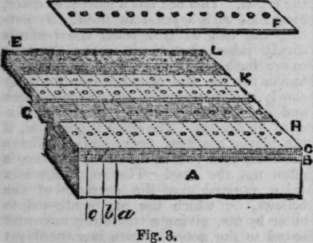
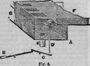
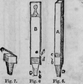
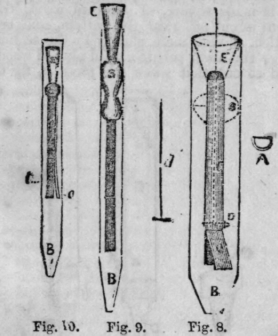
In the figure below, A is the wind-chest; B, the part of the sounding-board shown in fig 2 ; C, the upper part, forming its cover, and divided, as shown at L, E (the dotted lines show the position of the compartments beneath). It will be soon that a series of holes are made in the bottom of this upper tray corresponding with the compartments, both in itself and those below. Some boards, like F, slide into these upper divisions, the holes in which tally with those below, and also with others in the flat board, which covers the whole, shown at K and H. These boards, however, only tally when pulled out a little by means of the stops. G represents one so pulled out. Now, suppose all the slides pushed in but one, and the outer board put on, and, in the holes in this latter, pipes placed. If a valve is opened by the key pressed (say the first to the right, as before), the air will pass from the wind-chest into the channel between 1 and 2, and its only vent being through the first hole in the slide that is nulled out, it will pass by it into the pipe that is placed over it in the board covering the whole (shown at H and K); and so, in every note played, the row of pipes only over the slide that is drawn out can sound, as none of the other 6ets of holes tally. Thus we can, by means of stops or handles connected with these slides, use one or mere at pleasure, a, b, c are wires by which the valves are connected with the keys, which valves we will now explain. (Fig. 4). G is a part of the wind-chest, and F the sounding-board; H the valve, K the spring, B the key, turning on a centre, as does also the lever C. D is the wire from the valve. The divisions we stated in the sounding-board would run lengthwise between the valves, as shown by the dotted line. We think a glance at the diagram will make it all quite clear; and we would advise our young friends to read over, as far as this, several times, so as to get a clear idea of the construction before proceeding to learn about the pipes and other matters. We will now describe the construction of the pipes, beginning with the wooden ones. Fig. 5 represents one of these. It is made square, of reasoned wood; the front is cut oil', near the bottom, and bevelled, as seen more plainly by the section at c; the lower part is a solid plug of wood, and so cut that when the piece a, fig 6, is put on (marked b in fig. 5), a narrow slit is left just below the edge of the bevel. Through this slit (shown in the section and at a, fig. 7), the air rushes from the wind-chest, and being cut, as it were, by the bevel, produces a sound, deep or shrill, according to the length of the pipe; if the upper part is stopped by a plug, o. fig. 6, the sound is still more sharpened, and a higher note produced. In this way the wooden pipes may be tuned to any pitch. One set of the metal pipes are also made in a similar way; but there is another kind, called reed-pipes, the principle of which is somewhat different, and the sound of them more like that of a clarionet. Indeed, the latter instrument is made in a similar way, except that its reed is not made of metal. The following diagrams represent one of this kind. In figs. 8, 9, 10, B is the primary tube of metal, like the one in the last diagram ; within this is a half tube, c, of which a section is given at A. The flat part of this tube is covered by a slip of brass, the lower part of which is left to vibrate; this is marked o. In figs. 8 and 10, a piece of wood, S, is inserted in the outer pipe, forming a plug, and also a support for the inner tube, which is passed into it. Thus all the air that enters the outer pipe must pass through the inner tube, and in so doing it causes the part o to vibrate, which produces a sound. The tone is regulated by the wire d, shown dotted in fig. 8. The lower part of this wire rests on the reed, or vibrating slip o, and thus any length may be left to vibrate; and according as a long or short piece is left loose, the tone is deep or shrill. This wire passes through the plug S; E is another tube, also inserted in the piece of wood S, and is, in fact, a continuation of the inner tube. The shape of it varies according to the different style of tone required.
These are the "chief pipes in an organ. There are others, especially in large instruments ; but we must not lengthen this paper by describing them. We need only add that if a pipe of 12 inches long gives a certain note, one of 24 inches will give its octave below, and one of six inches an octave above. So, also, if an open pipe gives C, it will give the C above if closed, Thus it is easy to arrange the pipes, after one of a certain known length is fixed on for a fundamental note.
Continue to:
My Books

