


Laidlaw Apparatus And Method
Description
This section is from the book "Instrumental Insemination Of Queen Bees", by Otto Mackensen, Kenneth W. Tucker. Also available from Amazon: Instrumental Insemination Of Queen Bees.
Laidlaw Apparatus And Method
The Laidlaw apparatus for instrumental insemination (fig. 11) differs from that of Roberts and Mackensen in the way the queen is held and in the way the movement of the holding hooks and syringe is controlled by means of racks and pinions. The track on which the syringe is advanced is fixed, so that the queen is positioned beneath the syringe by moving the whole queen manipulator which holds the queen. The operation of instrumental insemination is quite similar to that with the Roberts and Mackensen apparatus.
The Laidlaw apparatus consists of two parts, a queen manipulator and a syringe manipulator.
The queen manipulator has a heavy circular base whose bottom surface is smooth and slides easily on the glass stage of a microscope for positioning the queen in relation to the syringe. The remainder of the queen manipulator is connected to the base by a ball and socket joint, which is tightened to a fixed position of optimal alignment of the queen to the syringe. The holding hooks are mounted by chucks on vertical racks and pinions, which in turn are mounted on horizontal racks and pinions to either side of the centrally located queen holder, with the sting hook to the right and the ventral hook to the left when the control knobs face the operator. The queen holder consists of two vertical surfaces, the left one fixed and the right one moveable. Pieces of foam rubber glued to each of these surfaces from the pads between which the queen is clamped. The moveable surface can be moved back and forth by a rack and pinion. The fixed surface is recessed into a block, so as to make a closed anesthetization chamber about the queen when she is clamped in position. Carbon dioxide gas is directed toward the queen's thoracic spiracles from ports located in either side wall of the chamber.
The syringe manipulator consists of a rack and pinion tract to which the syringe is clamped and permits movement up and down at the adjusted angle. The syringe manipulator is mounted from a post attached to the front of the microscope stage. The attachment from the post to the syringe manipulator includes joints by which the syringe manipulator may be adjusted to the correct angle in relation to the queen, but tightened securely once this adjustment is made.
The approximate alignment for the Laidlaw apparatus is with the queen manipulator tilted about 10° to the right of vertical, and the syringe manipulator about 20° to the right of vertical. The syringe tip should enter the queen's reproductive tract directed slightly towards the queen's vent rum about 10° from the queen's long axis. When the queen is positioned for insemination, the syringe and queen manipulator should be alined across the stage of the microscope in a line with the queen's dorsum towards about 1 o'clock and ventrum towards about 7 o'clock.
Because the alignment of the Laidlaw apparatus differs from that of the Roberts and Mackensen apparatus, the construction of holding hooks and of the valvefold probe differs.
Detailed plans for the Laidlaw insemination apparatus are available from Dr. Harry H. Laidlaw, Department of Entomology, University of California, Davis, Calif. 95616.
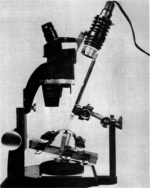
Figure 11. -Laidlaw insemination apparatus with Mackensen syringe. (Courtesy H. H. Laidlaw. )
With the Laidlaw apparatus, the operation of instrumental insemination consists of the same steps as with the Roberts and Mackensen apparatus, but the details of how some of these steps are accomplished differ. The major differences are the following:
Placing the queen into the queen holder is done with the queen already anesthetized, by holding the queen in one's hand along with a tube delivering carbon dioxide. The motionless queen is then grasped gently with one's left hand by the anterior part of her abdomen and suspended, head downward and dorsum to the right, into the opened queen holder, so that her dorsoventral body axis is in a straight line with the holding hooks and with her thorax opposite the foam rubber pads. The queen holder is then closed by turning the control knob with one's right hand until the queen is firmly clamped into position. Placing the queen into the queen holder is done while the queen manipulator is on the laboratory table to the left of the microscope; the action is easily done without magnification.
With the queen manipulator placed onto the stage of the microscope, the sting chamber is opened and kept spread open with the sting depressed with a pair of fine jeweler's forceps held in one's left hand. The sting hook and then the ventral hook are positioned by turning the appropriate control knobs for the racks and pinions, after which the forceps are withdrawn.
The queen is oriented in relation to the syringe by sliding the queen manipulator on the glass microscope stage. Since the syringe can be moved only upward and downward, and cannot be tilted or moved from side to side, even the final adjustment to get the syringe tip in position for insertion is made by moving the queen manipulator.
Inserting the syringe tip into the median oviduct with the Laidlaw apparatus differs only slightly from that operation with the Roberts and Mackensen apparatus. In moving the valvefold, the operator moves it toward 7 o'clock, rather than toward 9 o'clock. The syringe is advanced and withdrawn by turning the control knob for the rack and pinion on the syringe manipulator. Also, since the queen is nearly vertical, the valvefold is seen more readily, and one can often see through the vagina to the opening of the median oviduct when the valvefold is moved.
Continue to:


My Books

