


Manipulating Apparatus
Description
This section is from the book "Instrumental Insemination Of Queen Bees", by Otto Mackensen, Kenneth W. Tucker. Also available from Amazon: Instrumental Insemination Of Queen Bees.
Manipulating Apparatus
A good manipulating apparatus will not only support the parts already described but will hold the syringe and holding hooks so that their functioning ends can be moved in any direction smoothly and easily and yet remain exactly where placed when released. The apparatus illustrated in figure 6 fulfills these requirements, and the position of its parts can be reversed for a left-handed operator.
It has a heavy base to which are attached the mounting for the queen holder in the center and 3/8-inch posts at either side 4 1/2 inches apart. The left post supports the ventral hook mounting and the right post, the syringe mounting (above) and the sting hook mounting (below).
The queen holder mounting block can be rotated in a vertical plane or moved from side to side. After it is once adjusted according to the wishes of the operator it is tightly secured. It is provided with a spring so that the queen holder can be simply and quickly snapped in place and moved up or down or revolved for accurate positioning while the tension of the spring holds the queen holder in place. We suggest that the queen holder block be adjusted so that the queen holder leans 30° from vertical and makes a 10° angle with the syringe about as illustrated in figure 6 and changes be made later as desired.
Since the mountings for the syringe and holding hooks are similar, only the mounting of the ventral hook (fig. 9) will be described. The hook handle passes through holes in each end of a sheet metal holder. These holes are rounded at the bottom and inverted V-shaped at the top. A fiat spring pushes the handle upward into the inverted V. The tension of the spring can be adjusted so that the hook handle can be slid in and out with just the right amount of friction. The hook holder is seated in a tapered depression in its support block so that it can rotate in a vertical plane. It extends through the block as a bolt and is held in place by a spring washer and two nuts. The degree of friction between the hook holder and its seat is controlled by the tension of the spring, which is adjusted by the inner nut. The outer nut locks the inner nut in place. The support block consists of two parts which clamp onto the upright post permitting rotation in a horizontal plane and adjustment up or down on the post. The parts are held together by two bolts with coiled springs under the nuts. The amount of friction with the post is controlled by adjusting the tension of the springs. This arrangement makes it possible to move the end of the hook in any direction quickly and easily and have it remain exactly in the position it was in when released. A split collar under the block is tightened around the post to hold the block at the desired level.
An insemination apparatus similar to the one just described is available commercially.
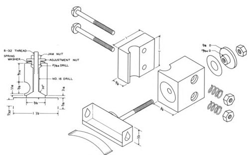
Figure 9. -Structural details of the ventral hook mounting with horizontal section through the principal axis. Dimensions are in inches.
Continue to:


My Books

