85. - Centre Of Gravity
Description
This section is from the book "The American House Carpenter", by R. G. Hatfield. Also available from Amazon: The American House Carpenter.
85. - Centre Of Gravity
The centre of gravity of a uniform prism or cylinder is in its axis, at the middle of its length; that of a triangle is in a line drawn from one angle to the middle of the opposite side, and at one third of the length of the line from that side; that of a right-angled triangle, at a point distant from the perpendicular equal to one third of the base, and distant from the base equal to one third of the perpendicular; that of a pyramid or cone, in the axis and at one quarter of the height from the base.
The centre of gravity of a trapezoid (a four-sided, figure having only two of its sides parallel) is in a line joining the centres of the two parallel sides, and at a distance from the longest of the parallel sides equal to the product of the length in the sum of twice the shorter added to the longer of the parallel sides, divided by three times the sum of the two parallel sides. Algebraically thus:
d = l (2a+B)/3 (a+b),
where d equals the distance from the longest of the parallel sides, l the length of the line joining the two parallel sides, and a the shorter and b the longer of the parallel sides.
Example. - A rafter 25 feet long has the larger end 14 inches wide, and the smaller end 10 inches wide: how far from the larger end is the centre of gravity located?
Here l = 25, a - 10/12, and b = 14/12,
hence d = l(2a+b) = 25(2x10/12+14/12 = 25x34/12 = 25x34 =
3(a+b) 3(10/12+14/12) 3x24/12 3x24
850/72 = 11.8 = 11 feet 9 5/8 inches nearly.
In irregular bodies with plain sides, the centre of gravity may be found by balancing them upon the edge of a prism - upon the edge of a table - in two positions, making a line each time upon the body in a line with the edge of the prism, and the intersection of those lines will indicate the point required. Or suspend the article by a cord or thread attached to one corner or edge; also from the same point of suspension hang a plumb-line, and mark its position on the face of the article; again, suspend the article from another corner or side (nearly at right angles to its former position), and mark the position of the plumb-line upon its face; then the intersection of the two lines will be the centre of gravity.
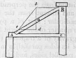
Fig. 32.
86. - Effect of the Weight of Inclined Beams, - An inclined post or strut supporting some heavy pressure applied at its upper end, as at Fig. 25, exerts a pressure at its foot in the direction of its length, or nearly so. But when such a beam is loaded uniformly over its whole length, as the rafter of a roof, the pressure at its foot varies considerably from the direction of its length. For example, let A B (Fig. 32) be a beam leaning against the wall B e, and supported at its foot by the abutment A, in the beam A c, and let 0 be the centre of gravity of the beam. Through o draw the vertical line b d, and from B draw the horizontal line B b, cutting b d in b; join b and A, and b A will be the direction of the thrust. To prevent the beam from loosing its footing, the joint at A should be made at right angles to bA. The amount of pressure will be found thus: Let b d (by any scale of equal parts) equal the number of tons upon the beam A B; draw d e parallel to B b; then b; c (by the same scale) equals the pressure in the direction b A; and c d the pressure against the wall at B - and also the horizontal thrust at A, as these are always equal in a construction of this kind.
The horizontal thrust of an inclined beam (Fig. 32) - the effect of its own weight - may be calculated thus:
Rule. - Multiply the weight of the beam in pounds by its base, A C, in feet, and by the distance in feet of its centre of gravity, o (see Art. 85), from the lower end, at A, and divide this product by the product of the length, A B, into the height, B C, and the quotient will be the horizontal thrust in pounds. This may be stated thus: H =d b w/h l, where d equals the distance of the centre of gravity, 0, from the lower end; b equals the base, A C; w equals the weight of the beam; h equals the height, B C; l equals the length of the beam; and H equals the horizontal thrust.
Example. - A beam 20 feet long weighs 300 pounds; its centre of gravity is at 9 feet from its lower end; it is so inclined that its base is 16 feet and its height 12 feet: what is the horizontal thrust?
Here d b w/h l becomes9x16x300/12x20=9x4x25/5=9x4x5
= 180 =H == the horizontal thrust.
This rule is for cases where the centre of gravity does not occur at the middle of the length of the beam, although it is applicable when it does occur at the middle; yet a shorter rule will suffice in this case, and it is thus:
Rule. - Multiply the weight of the rafter in pounds by the base, A C (Fig. 32), in feet, and divide the product by twice the height, B C, in feet, and the quotient will be the horizontal thrust, when the centre of gravity occurs at the middle of the beam.
If the inclined beam is loaded with an equally distributed load, add this load to the weight of the beam, and use this total weight in the rule instead of the weight of the beam. And generally, if the centre of gravity of the combined weights of the beam and load does not occur at the centre of the length of the beam, then the former rule is to be used.
In Fig. 33, two equal beams are supported at their feet by the abutments in the tie-beam. This case is similar to the last: for it is obvious that each beam is in precisely the position of the beam in Fig. 32. The horizontal pressures at B, being equal and opposite, balance one another; and their horizontal thrusts at the tie-beam are also equal. (See Art.
78 - Fig. 25.) When the height of ft roof (Fig. 33) is one fourth of the span, or of a shed (Fig. 32) is one halt the span, the horizontal thrust of a rafter, whose centre of grav- ity is at the middle of its length, is exactly equal to the weight distributed uniformly over its surface.
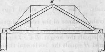
Fig. 33.
In shed or lean-to roofs, as Fig. 32, the horizontal pressure will be entirely removed if the bearings of the rafters, as A and B (Fig. 34), are made horizontal - provided, however, that the rafters and other framing do not bend between the points of support. If a beam or rafter have a natural curve, the convex or rounding edge should be laid uppermost.
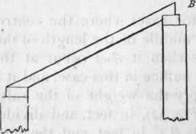
Fig. 34.
87. - Effect Of Load On Beam
The strain in a uniformly loaded beam, supported at each end, is greatest at the middle of its length. Hence mortices, large knots, and other defects should be kept as far as possible from that point; and in resting a load upon a beam, as a partition upon a floor-beam, the weight should be so adjusted, if possible, that it will bear at or near the ends.
Twice the weight that will break a beam, acting at the centre of its length, is required to break it when equally distributed over its length; and precisely the same deflection or sag will be produced on a beam by a load equally distributed that five eighths of the load will produce if acting at the centre of its length.
Continue to:
My Books

