Plan No. 5: Water Supply, Double-Boiler System
Description
This section is from the book "A Treatise On Architecture And Building Construction Vol4: Plumbing And Gas-Fitting, Heating And Ventilation, Painting And Decorating, Estimating And Calculating Quantities", by The Colliery Engineer Co. Also available from Amazon: A Treatise On Architecture And Building Construction.
Plan No. 5: Water Supply, Double-Boiler System
194. Fig. 75 shows how the lower floors of a building may be supplied with hot and cold water from the city mains, while the upper floors are supplied from a tank, one waterback being employed to heat the water for the entire building.
The dotted line A B shows the height to which the street water will rise, therefore, the fixtures above that are supplied from the tank a. Of course, those below A B may also be supplied from a, but to economize pumping, the piping is so arranged that they can be supplied direct from the street.
An "Ericsson" hot-air pumping engine r is shown in the cellar, having its suction pipe b connected to the main c, and its delivery pipe s leading over and into the tank a. The engine is supplied with a gas burner, and can be stopped when the tank is full by the arrangement shown at the wheel valve d over the basement sink. A water-line indicator e is placed over the kitchen sink, so that the servants may see how much water is in the tank. This sliding indicator is attached to a float in the tank by a chain or wire, working over two pulleys. When the tank is empty, the float falls with the water and raises the indicator to the top of the slide board, and when filled again, the indicator falls towards the bottom. The slide board is graduated in feet and inches, and if the indicator is regulated properly, it will indicate the depth of water in the tank very accurately. This plate also shows hot-water circulation to all the fixtures, except the kitchen sink and laundry tubs, the branches to which are short. Circulation to these fixtures may be obtained by dropping the return pipe below the boiler level, and connecting the branches to the returns. If such connections are made, however, there will be danger of hot water being drawn from the bottom of the boiler along with hot water from the flow pipes, unless check-valves are used on the returns near the boiler. Some plumbers object to check-valves on returns, and, consequently, connect these fixtures as shown.

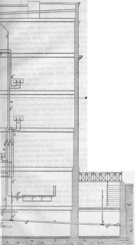
The check-valve f will admit water to flow from the outer boiler or street main to the inner boiler, when the pressure in the inner boiler is less than that in the outer one, but will prevent any water in the inner boiler from passing out again.
A lever-handled stop-cock g, when opened, will feed the outer boiler and all the fixtures on the lower floors with tank water. Of course, when this cock is opened, the valve on the street service pipe must be closed, otherwise the tank water will flow back to the street mains. If the cock g be used much, a swinging check should be placed on the main service pipe c.
The sediment cock for the inner boiler is shown at h, and for the outer boiler at i.
The waterback is connected to the outer boiler in the ordinary manner, and heats water for the entire building. The telltale j flows into the pan of the automatic shut-off valve d, so that when the tank is full, the telltale will fill the pan with water, the weight of which will close the valve and stop the engine.
The rising main supplies cold water to the outer boiler, kitchen sink, and fixtures on first and second floors above, except the water closet on second floor, which is supplied from the tank, because it is too near A B.
The hot supply to third and fourth floors, or tank hot, flows through l to the top floor, where an expansion pipe is taken off its highest point and led over the tank. This pipe then continues and drops to supply the wash basin to the right on the third floor. It is then continued back to the boiler by the return pipe m. The hot supply to basement and first and second floors, flows through n and n1; the end of n being run up to and over the tank, as an expansion pipe and air vent. The pipes p, p1 are for the circulation of the street hot supply. If desired, a small pipe may be run from the hot supply branch q to the tank to carry off any air that might accumulate there and stop circulation.
The pipe t acts only as a relief pipe, and may or may not be used.
In this drawing it is assumed that the street water will not at any time be sufficient to rise into the tank; otherwise, the expansion and relief pipes would be omitted, or carried considerably above the tank, to prevent the temporarily increased main pressure from forcing hot water into the tank.
The student should carefully study the different lines of pipes in the five preceding figures until he thoroughly understands the function of each pipe, and thoroughly grasps the principles of supply and distribution of hot and cold water, and the proper construction of soil, waste, vent, and drain pipe lines.
Continue to:
My Books

