The Steel Square As Applied In Roof Framing
Description
This section is from the book "Cyclopedia Of Architecture, Carpentry, And Building", by James C. et al. Also available from Amazon: Cyclopedia Of Architecture, Carpentry And Building.
The Steel Square As Applied In Roof Framing
Roof framing at present is as simple as it possibly can be, so that any attempt at a new method would be superfluous. There may, however, be a certain way of presenting the subject that will carry with it almost the weight assigned to a new theory, making what is already simple still more simple.

Fig. 10. Diagram for Finding Pitches of Various Degrees by Means of the Steel Square.

Fig. 11. Square Applied to Determine Relative Length of Run for Rafter and Hip.
The steel square is a mighty factor in roof framing, and without doubt the greatest tool in practical potency that ever was invented for the carpenter. With its use the lengths and bevels of every piece of timber that goes into the construction of the most intricate design of roof, can easily be obtained, and that with but very little knowledge of lines.

Fig. 12. Use of Square to Determine Length of Run for Rafters on Corners Other than 45°.
In roofs of equal pitch, as illustrated in Fig. 14, the steel square is all that is required if one properly understands how to handle it.

STRUCTURAL WOODEN ROOF TRUSS IN FIRST PRESBYTERIAN CHURCH, SYRACUSE, N. Y.
Tracy & Swartwout, Architects; Ballantyne & Evans, Associated. Reproduced by courtesy of " The Architectural Revieiw".
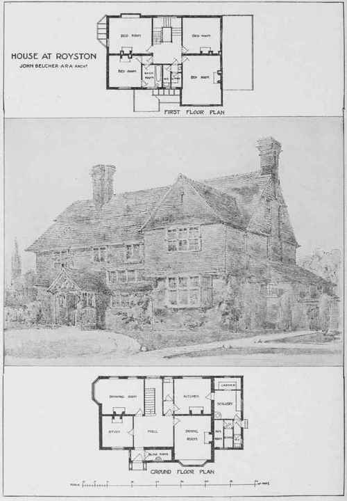
HOUSE AT ROYSTON, ENGLAND.
John Belcher, A. R. A., Architect.
Walls Built of Red Bricks with Overhanging Tiles and a Tiled Roof. The Entrance Porch is of Oak Reprinted by permission from "Modern Cottage Architecture," John Lane Co., Publishers.
What is meant by a pitch of a roof, is the number of inches it rises to the foot of run.
In Fig. 15 is shown the steel square with figures representing the various pitches to the foot of run. For the 1/2-pitch roof, the figures as shown, from 12 on tongue to 12 on blade, are those to be used on the steel square for the common rafter; and for 3/8 pitch, the figures to be used on the square will be 12 and 9, as shown.
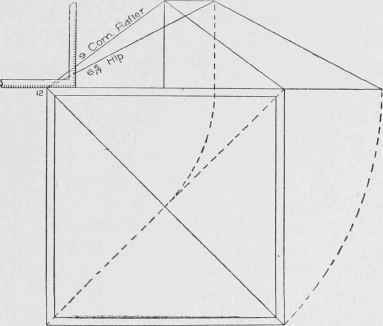
Fig. 13. Method of Finding Relative Height of Hip or Valley per Foot of Run to that of Common Rafter.

Fig. 14. Diagram to Illustrate Use of Steel Square in Laying Out Timbers of Roofs of Equal Pitch.
To understand this figure, it is necessary only to keep in mind that the pitch of a roof is reckoned from the span. Since the run in each pitch as shown is 12 inches, the span is two times 12 inches, which equals 24 inches; hence, 12 on blade to represent the foot run, and 12 on tongue to represent the rise over 1/2 the span, will be the figures on the square for a 1/2-pitch roof.
For the 3/83 pitch, the figures are shown to be 12 on tongue and 9 on blade, 9 being 3/8 of the span, 24 inches.
The same rule applies to all the pitches. The 1/6 pitch is shown to rise 4 inches to the foot of run, because 4 inches is 1/6 of the span, 24 inches, the 1/3 pitch is shown to rise 8 inches to the foot of run, because 8 inches is 1/3 of the span, 24 inches; etc.
The roof referred to in Figs. 16 and 17 is to rise 9 inches to the foot of run; it is therefore a 3/8-pitch roof. For all the common rafters, the figures to be used on the square will be 12 on blade to represent the run, and 9 on tongue to represent the rise to the foot of run; and for all the hips and valleys, 17 on blade to represent the run, and 9 on tongue to represent the rise of the roof to the foot of run.
Why 17 represents the run for all the hips and valleys, will be understood by examining Fig. 19, in which 17 is shown to be the diagonal of a foot square.
In equal-pitch roofs the corners are square, and the plan of the hip or valley will always be a diagonal of a square corner as shown at 1, 2, 3, and 5 in Fig. 14
In Fig. 18 are shown 1/6 pitch, 3/8 pitch and 1/2 pitch over a square corner.
The figures to be used on the square for the hip, will be 17 for run in each case. For the 1/6 pitch, the figures to be used would be 17 inches run and 4 inches rise, to correspond with the 12 inches run and 4 inches rise of the common rafter. For the 3/8 pitch, the figures to be used for hip would be 17 inches run and 9 inches rise, to correspond with the 12 inches run and 9 inches rise of the common rafter; and for the 1/2 pitch, the figures to be used on the square will be 17 inches run and 12 inches rise, to correspond with the 12 inches run and 12 inches rise of the common rafter.
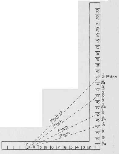
Fig. 15. Steel Square Giving Various Pitches to Foot of Run.
It will be observed from above, that in all cases where the plan of the hip or valley is a diagonal of a square, the figures to be used on the square for run will be 17 inches; and for the rise, whatever the roof rises to the foot of run. It should also be remembered that this is the condition in all roofs of equal pitch, where the angle of the hip or valley is a 45-degree angle, or, in other words, where we have the diagonal of a square.

Fig. 16. Method of Laying Out Common Rafters of a 3/8-Pitch Roof.
It has been shown in Fig. 12 how other figures for other plan angles may be found; and that in each case the figures for run vary according to the plan angle of the hip or valley, while the figure for the height in each case is similar.
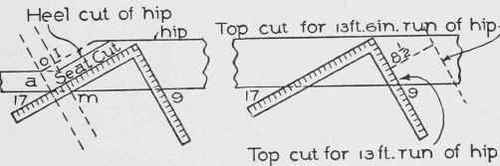
Fig. 17. Method of Laying Out Hips and Valleys of a 3/8-Pitch Roof.
In Fig. 14 are shown a variety of runs for common rafters, but all have the same pitch; they rise 9 inches to the foot of run. The main roof is shown to have a span of 27 feet, which makes the run of the common rafter 13 feet 6 inches. The run of the front wing is shown to be 10 feet 4 inches; and the run of the small gable at the left corner of the front, is shown to be 8 feet.
The diversity exhibited in the runs, and especially the fractional part of a foot shown in two of them, will afford an opportunity to treat of the main difficulties in laying out roof timbers in roofs of equal pitch. Let it be determined to have a rise of 9 inches to the foot of run; and in this connection it may be well to remember that the proportional rise to the foot run for roofs of equal pitch makes not the least difference in the method of treatment.
To lay out the common rafters for the main roof, which has a run of 13 feet 6 inches,proceed as shown in Fig. 16.
Take 12 on the blade and 9 on the tongue, and step 13 times along the rafter timber. This will give the length of rafter for 13 feet of run. In this example, however, there is another 6 inches of run to cover. For this additional length, take 6 inches on the blade (it being 1/2 a foot run) for run, and take 1/2 of 9 on the tongue (which is 4 1/2 inches), and step one time. This, in addition to what has already been found by stepping 13 times with 12 and 9, will give the full length of the rafter.
The square with 12 on blade and 9 on tongue will give the heel and plumb cuts.
Another method of finding the length of rafter for the 6 inches is shown in Fig. 16, where the square is shown applied to the rafter timber for the plumb cut. Square No. 1 is shown applied with 12 on blade and 9 on tongue for the length of the 13 feet. Square from this cut, measure 6 inches, the additional inches in the run; and to this point move the square, holding it on the side of the rafter timber with 12 on blade and 9 on tongue, as for a full foot run.
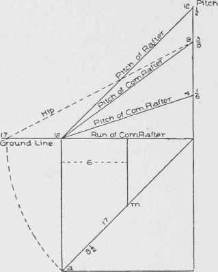
Fig. 18. Method of Laying Out Hips and Rafters for Roofs of Various Pitches over Square Corner.
It will be observed that this method is easily adapted to find any fractional part of a foot in the length of rafters.
In the front gable, Fig. 14, the fractional part of a foot is 4 inches to be added to 10 feet of run; therefore, in that case, the line shown measured to 6 inches in Fig. 16 would measure only 4 inches for the front gable.
Continue to:
My Books

