181. Footings
Description
This section is from the book "Cyclopedia Of Architecture, Carpentry, And Building", by James C. et al. Also available from Amazon: Cyclopedia Of Architecture, Carpentry And Building.
181. Footings
The three requirements of a footing course are:
(1) That the area shall be such that the total load divided by the area shall not be greater than the allowable unit-pressure on the subsoil.
(2) That the line of pressure of the wall (or pier) shall be directly over the center of gravity (and hence the center of upward pressure) of the base of the footings.
(3) That the footing shall have sufficient structural strength so that it can distribute the load uniformly over the subsoil.
When it has been determined with sufficient accuracy how much pressure per square foot may be allowed on the subsoil (see sections 172-176), and when the total load of the structure has been computed, it is a very simple matter to compute the width of continuous footings or the area of column footings.
The second requirement is very easily fulfilled when it is possible to spread the footings in all directions as desired, as shown in Fig. 43. A common exception occurs when putting up a building which entirely covers the width of the lot. The walls are on the building line; the footings can expand inward only. The lines of pressure do not coincide, as shown in Fig. 40. A construction as shown in the figure will almost inevitably result in cracks in the building, unless some special device is adopted to prevent them. One general method is to introduce a tie of sufficient strength from a to b. The other general method is to introduce cantilever beams under the basement, which either extend clear across the building or else carry the load of interior columns so that the center of gravity of the combined loads will coincide with the central pressure line of the upward pressure of the footings.
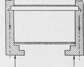
Fig. 40. Construction where Lines of Downward and Upward Pressure on Footings do not Coincide.
The third requirement practically means that the thickness of the footing (bc, Fig. 41) shall be great enough so that the footing can resist the transverse stresses caused by the pressure of the subsoil on the area between c and d. When the thickness must be made very great (such as fh, Fig. 42), on account of the wide offset gh, material may be saved by cutting out the rectangle e k m l. The thickness m o is computed for the offset g o, just as in the first case; while the thickness k m of the second layer may be computed from the offset k f. Where the footings are made of stone or of plain concrete, whose transverse strength is always low, the offsets are necessarily small; but when using timber, reinforced concrete, or steel I-beams, the offsets may be very wide in comparison with the depth of the footing. 182. Calculation of Footings. The method of calculation is to consider the offset of the footing as an inverted cantilever which is loaded with the calculated upward pressure of the subsoil against the footing. If Fig. 41 is turned upside down, the resemblance to the ordinary loaded cantilever will be more readily apparent. Considering a unit-length (I) of the wall and the amount of the offset o (= dc in Fig. 41), and calling P the unit-pressure from the subsoil, we have P o l as the pressure on that area, and its lever-arm about the point c is 1/2 o. Therefore its moment = 1/2 P o2 l. If t represents the thickness b c of the footing, the moment of resistance of that section = 1/6Rlt2, in which R = the unit-compression (or unit-tension) in the section. We therefore have the equation:

Fig. 41. Transverse Stresses in Footing Determining Its Thickness.

Fig. 42. Saving of Material in Very Thick Footing.
1/2Po2l = 1/6Rlt2.
By transposition,
(2)
The fraction - is the ratio of the offset to its thickness. The solution of the above equation, using what are considered to be conservatively safe values for R for various grades of stone and concrete, is given in Table XII.
Table XII. Ratio Of Offset To Thickness For Footings Of Various Kinds Of Masonry
Kind of Masonry | Modulus of Rupture ( Minimum and Maximum Values) | Average | Assumed Safe Value (R) | Pressure on Bottom of Footing (Tons per Square Foot) | ||||||
0.5 | 1.0 | 1.5 | 2.0 | 2.5 | 3.0 | 3.5 | ||||
1,200-1,365 | 1,280 | 130 | 2.5 | 1.8 | 1.45 | 1.25 | 1.1 | 1.0 | 0.95 | |
450- 900 | 675 | 70 | 1.8 | 1.3 | 1.05 | 0.9 | 0.8 | 0.75 | 0.7 | |
135-1,100 | 525 | 55 | 1.6 | 1.15 | 0.95 | 0.8 | 0.75 | 0.65 | 0.6 | |
Concrete(plain) | ||||||||||
1:2:4 | 400- 480 | 440 | 75 | 1.9 | 1 35 | 1 1 | 0 95 | 0.85 | 0 75 | 0.7 |
1:3:6 | 213- 246 | 230 | 40 | 1.4 | 1.0 | 0.8 | 0.7 | 0.6 | 0.55 | 0.5 |
183. Example The load on a wall has been computed as 19,000 pounds per running foot of the wall, which has a thickness of 18 inches just above the footing. "What must be the breadth and thickness of granite slabs which may be used as a footing on soil which is estimated to bear safely a load of 2.0 tons per square foot?
Solution. Dividing the computed load (19,000) by the allowable unit-pressure (2.0 tons = 4,000 pounds), we have 4.75 feet as the required width of the footing.
1/2 (4.75 -- 1.5) = 1 625 feet, the breadth of the offset (b).
From the table we find that for a subsoil loading of 2.0 tons per square foot, the offset for granite may be 1.25 times its thickness. Therefore, 1.625 = 1.30 feet =15.6 inches, is the required thickness of
1 . 25 the footing.
The computation of the dimensions of such footings when they are made of reinforced concrete is taken up during the development of this specialized form of Masonry in Part III.
Although brick can be used as a footing course, the maximum possible offset (no matter how strong the brick may be) can only be a small part of the length of the brick - the brick being laid perpendicular to the wall. One requirement of a footing course is that the blocks shall be so large that they will equalize possible variations in the density and compressibility of the subsoil. This cannot be done by bricks or small stones. Their use should therefore be avoided in footing courses.
Continue to:
My Books

