Approximate Blanks For Curved Mouldings Hammered By Machine
Description
This section is from the book "Cyclopedia Of Architecture, Carpentry, And Building", by James C. et al. Also available from Amazon: Cyclopedia Of Architecture, Carpentry And Building.
Approximate Blanks For Curved Mouldings Hammered By Machine
The principles employed in averaging the profile for a moulding to be rolled or hammered by machine do not differ to any material extent from those used in the case of mouldings hammered by hand.
Fig. 351 shows the general method of averaging the profile of a moulding in determining the radius of the blank or pattern. It will be seen that A B is drawn in such a manner, so to speak, as to average the inequalities of the profile D C required to be made. Thus distances a and b are equal, as are the distances c and d, and e and /. It is very difficult to indicate definite rules to be observed in drawing a line of this kind, or, in other words, in averaging the profile. Nothing short of actual experience and intimate knowledge of the material in which the moulding is to be made, will enable the operator to decide correctly in all cases. There is, however, no danger of making very grave errors in this respect, because the capacity of the machines in use is such, that, were the pattern less advantageously planned in this particular than it should be, still, by passing it through the dies or rolls an extra time or two, it would be brought to the required shape.
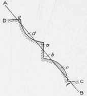
Fig. 351.
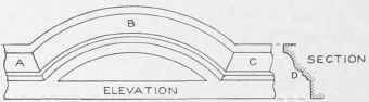
Fig. 352.
In Fig. 352 is shown a part elevation of a circular moulding as it would occur in a segmental pediment, window cap, or other structure arising in sheet-metal cornice work. H shows the curved rnoulding, joining two horizontal pieces A and C, the true section of all the moulds being shown by D.
In this connection it may be proper to remark that in practice, no miters are cut on the circular blanks, the miter-cuts being placed on the horizontal pieces, and the circular moulding trimmed after it has been formed up.
In Fig. 353 is shown the method of obtaining the blanks for mouldings curved in elevation, no matter what their radius or profile may be. First draw the center line A B, and, with the desired center, as B, describe the outer curve A. At right angles to A B, in its proper position, draw a section of the profile as shown by C D. From the various members in this section, project lines to the center line A B, as 1, 2, 3, and 4; and, using B as center, describe the various arcs and complete the elevation as shown by A B C in Fig. 352, only partly shown in Fig. 353. In the manner before described, average the profile C D by the line c d, extending it until it intersects the line drawn through the center B at right angle to A B, at E. Then E is the center from which to strike the pattern. Centrally on the section C D, establish e on the line c d, where it intersects the mould, and take the stretchout from e to C and from e to D, and place it as shown respectively from e to c and from c to d on the line c d. Now, using E as center, with radii equal to E d, E e, and E c, describe the arcs d' d", e' e", and c' c". Draw a line from c' to E, intersecting the middle and inner arc at e' and d'. The arc e' e" then becomes the measuring line to obtain the length of the pattern, the length being measured on the arc 2 in elevation, which corresponds to the point e in section.
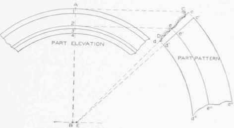
Fig. 353.
In Fig. 354 is shown the elevation of a moulding A curved in plan B, the arc being struck from the given point a. This is apt to occur when the moulding or cornice is placed on a building whose corner is round. To obtain the pattern when the moulding is curved in plan, proceed as shown in Fig. 355. Draw the section of the moulding, as A B, A C being the mould for which the pattern is desired. C B represents a straight strip which is attached to the mould after it is hammered or rolled to shape. In practice the elevation is not required. At pleasure, below the section, draw the horizontal line E D. From the extreme or outside edge of the mould, as b, drop a line intersecting the horizontal line E D at E. Knowing the radius of the arc on b in section, place it on the line E D, thus obtaining the point D. With D as center, describe the arc E F, intersecting a line drawn at right angle to E D from D. Average a line through the section, as G H, intersecting the line D F, drawn vertical from the center D, at J. Establish at pleasure the stationary point a, from which drop a line cutting E D at a'. Using D as center, and with D a' as radius, describe the arc a' a", which is the measuring line when laying out the pattern. Now take the stretchouts from a to b and from a to c, and place them on the averaged line from a to G and from a to H respectively. Using J as center, with radii extending to the various points G, a, and H, describe the arcs GG1, a a"',and H H1. On the arc a' a'", the pattern is measured to correspond to tin-arc a' a" in plan.
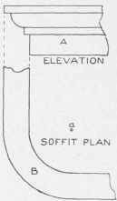
Fig. 354.
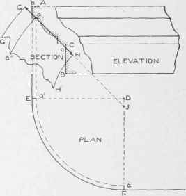
Fig. 355.
In Fig. 356 is shown a front view of an ornamental bull's-eye window, showing the circular mould A B C D, which in this case we desire to lay out in one piece, so that, when hammered or rolled in the machine, it will have the desired diameter. The same principles can be applied to the upper mould E F, as were used in connection with Figs. 352 and 353.
To obtain the blank for the bull's-eye window shown in Fig. 356 proceed as shown in Fig. 357. Let A B C D represent the elevation of the bull's-eye struck from the center C. Through E draw the horizontal and perpendicular lines shown. In its proper position, draw a section of the window as shown by F G. Through the face of the mould, as H 1, average the line H1 I1, . extending it until it intersects the center line B D at J. Where the average line intersects the mould at a, establish this as a stationary point; and take the stretchouts from a to I and from a to H, and lay them off on the line H1 I1 from a to I1 and a to H1 respectively. As 1 5 in elevation represents the quarter-circle on the point a in section, divide this quarter-circle into equal spaces, as shown. Now, with radii equal to J I1, J a, and J H1, and with J in Fig. 358 as center, describe the arcs H H, a a, and I I. From any point, as H, on one side, draw a line to J, intersecting the middle and inner arcs at a and I. Take the stretchout of the quarter-circle from 1 to 5 in elevation in Fig. 357, and place it on the arc a a as shown from 1 to 5. Step this off four times, as shown by 5', 5", and 5'". From J draw a line through 5'", intersecting the inner and outer arcs at I and H. Then will H a a H be the full pattern.
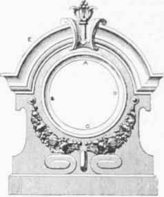
Fig. 356.
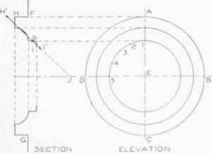
Fig. 257.
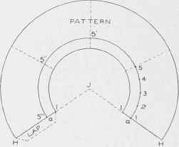
Fig. 358.
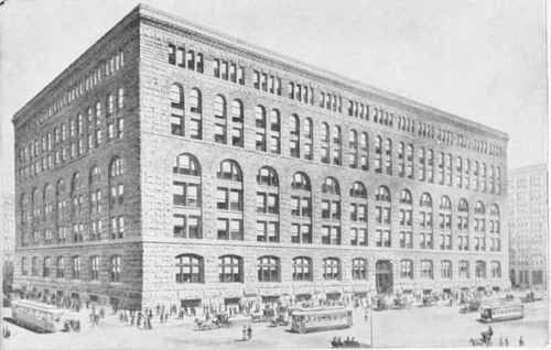
MARSHALL FIELD WH0LESALE STORE, CHICAGO, ILL.
H. H. Richardson and Shepley, Rutan & Coolidge, Architects. Granite Exterior
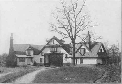
GATE LODGE OF J. H. MOORE AT LAKE GENEVA, WIS.
Jarvis Hunt, Architect, Chicago, I11.
Roofs Covered with Shingle Tiles, Dull Browns and Dull Greens, the Tile for the Gables being Specially Burned.
Reproduced by Courtesy of Ludovici- Celadon Company.
Continue to:
My Books

