Spur Gears
Description
This section is from the book "Modern Shop Practice", by Howard Monroe Raymond. Also available from Amazon: Modern Shop Practice.
Spur Gears
C = Width of arm extended to pitch line (inches), c = Distance from neutral axis to outer fiber (inches). D=Pitch diameter of gear (inches). F=Face of gear (inches). f =Clearance of tooth at bottom (inches). G=Thickness of arm extended to pitch line (inches). H=Thickness of tooth at any section (inches). h = Depth of rectangular section of arm (inches). I = Moment of inertia. K=Thickness of rim (inches). L= Distance from top of tooth to any section (inches).
N=Number of teeth, n = Number of arms. P=Diametral pitch (teeth per inch of diameter). p1= Circular pitch (inches). Q, Q1=Normal pressure between teeth (lbs.). K.R1=Resultant pressure between teeth (lbs.), r, r1 = Radius of pitch circles (Inches). S= Fiber stress of material (lbs. per sq. in.). s = Addendum of tooth (inches)=Dedendum of tooth. t - Thickness of tooth at pitch line (inches). W=Load at pitch line (lbs.). y = Coefficient for "Lewis" formula.
Analysis
If a cylinder be placed on a plane surface, with its axis parallel to the plane, an attempt to rotate the cylinder about its axis would cause it to roll on the plane.
Again, if two cylinders be provided with axial bearings, and be slightly pressed together, motion of one about its axis will cause a similar motion of the other, the two surfaces rolling one on the other at their common tangent line. If moved with care, there will be no slipping in either of the above cases - which is explained by the fact that no matter how smooth the surfaces may appear to be, there is still sufficient roughness to make the little irregularities interlock and act like minute teeth.
The magnitude of the force possible to be transmitted depends not only on the roughness of the surfaces, but on the amount of pressure between them. Suppose that one cylinder is a part of a hoisting drum, on which is wound a rope with a weight attached. "We can readily make the weight so great that, no matter how hard we press the two cylinders together, the driving cylinder will not turn the hoisting cylinder, but will slip past it. If now, instead of increasing the pressure, which is detrimental both to cylinders and bearings of same, we increase the coarseness of the surfaces, or, in other words, put teeth of appreciable size on these surfaces, we attain the desired result of positively driving without excessive side pressure.
These artificial projections, or teeth, must fit into one another; hence the surfaces of the original cylinders, having been broken up into alternate projections and hollows, have entirely disappeared to the eye; they nevertheless exist as ideal or imaginary surfaces, which roll together with the same surface velocities as if in bodily form, provided that the curves of the teeth are correctly formed. Several mathematical curves are available for use as tooth outlines, but in practice the involute and cycloidal curves are the only ones used for this purpose.
The ideal surfaces are known as pitch cylinders or pitch circles. In Fig. 32 is shown an end view of such a pair of cylinders in contact at their pitch point F. In gear calculations we assume that there is no slip between the pitch circles, acting as driving cylinders; hence the speeds of the two pitch circles at the pitch point are equal. If M and M1 be the revolutions per minute of the cylinders respectively, r and r1, their radii, then 2 π r M = 2 π r1M1; or, M / M1 = r1 /r., (60)
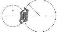
Fig. 32.
That is, the number of revolutions varies inversely as the radiiing of the pitch circles, and the velocity ratio proportional to.
As the surfaces of the teeth slide together, frictional resistance is produced at their point of contact. This force is widely variable, depending on the material and condition of the tooth surfaces, whether smooth and well lubricated, or rough and gritty. As this resistance acts in conjunction with the normal force between the teeth, we may construct a parallelogram of forces on these two as a base, the resultant pressure between the teeth being slightly changed thereby, as shown in Fig 33.
Assuming a coefficient of friction μ, the force of friction is ft Q or μ Q1 and the resultant pressure R or R1.
Tooth B of the follower is therefore under a heavy bending moment measured by the product RL, L being the perpendicular distance from the center of the tooth at its base to the lino of the force. This tooth also has a relatively small compressive stress due to the resolved part of R along the radius, and a relatively small shearing stress duo to the resolved part of R along a tangent to the pitch circle.
Tooth D of the driven wheel or follower has a relatively large shearing stress, a small bending moment, and practically no direct compressive stress.
Tooth A of the driving wheel or driver has a relatively large shearing stress, a small bending moment, and small compressive stress.
Tooth C of the driver has a largo bending moment, but small compressive and shearing stresses.
The conditions as noted above are not those of every pair of gears, in fact they vary with every difference of pitch circle, or of detail and position of tooth. It is true, however, that in nearly all cases in practice the bending stress is the controlling one from a theoretical standpoint. Moreover, the designer must consider the form and strength of the tooth when it is under the condition of maximum moment. This evidently, from the above, occurs at the beginning of contact, for the follower teeth; and at the end of contact, for the driver teeth. In the particular case illustrated in Fig. 33, if the material in both gears were the same, tooth C, being the weaker at the root, would probably break before B; but if C were of steel, and B of cast iron, B might break first.
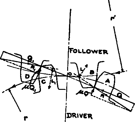
Fig. 33.
Continue to:
My Books

