Octagonal Fountain In Sheet Metal
Description
This section is from the book "Cassell's Cyclopaedia Of Mechanics", by Paul N. Hasluck. Also available from Amazon: Cassell's Cyclopaedia Of Mechanics.
Octagonal Fountain In Sheet Metal
Fig. 1 shows an elevation of a greenhouse fountain which could be made of copper or zinc. The parts A2, B2, and the moulded part of the foot C2 are of curved sheet metal, which, when mitred at the different edges, will form an octagonal basin, the centre piece and foot resting upon a circular base. The fountain is supplied through the pipe shown projecting at the base, and on the opposite side of the fountain an overflow pipe should be arranged, the top of which projects through the bottom of the part A2 to a height equal to the depth of water that is to remain in the basin. To work the patterns for forming the fountain, draw to the required size an elevation as shown by Fig. 1, the curved outline on the left-hand side representing the true shape of a section of one face when cut by a vertical plane containing the line a 0 in plan (Fig. 2). To draw the plan, take half the diameter of the top of the basin as radius, and any point on the centre line, say O (Fig. 2), as centre. Draw the circle shown, then inscribe an octagon within the circle and so arrange it that the side of the octagon containing the points b b2 is at right angles to the ground line. Bisect this side of the octagon and draw the line of bisection 0 b. Now divide the curve A H (Fig. 1) into any convenient number of equal parts, and draw projectors from these division points, A, B, B', etc., to join the mitre line b20 (Fig. 2). To work the pattern for the basin, transfer the divisions B to H (Fig. 1) to a straight line, as shown by B, B', C, D, E, F, G, and H (Fig. 3). Through each of these division points draw lines at right angles to and on both sides of the centre line. Now take the length b b2 (Fig. 2), and set it off on each side of the centre line (Fig. 3) as Bb2. Also transfer the lengths blb3, ccl, dd1, etc., from the plan (Fig. 2) to the lines with corresponding letters in Fig. 3, and through the points found draw a curve on each side of the pattern, as b2, b3, c1, d1 etc. Then take the radius O a from the plan (Fig. 2), and with this length mark a point from b2 at O (Fig. 3); then, using O as centre, draw the top curve A b2 to complete the basin pattern. The pattern for the centre piece and foot (Fig. 1) is worked in the same way, the divisions from H to Y being the distances to be transferred to the centre line (Fig. 4). The widths to be set off on each side of the centre line are shown in plan on the octagon face B1 (Fig. 2), those for the foot being shown on the face C1 (Fig. 2). Fig. 6 is the pattern for the circle forming the top of the cylindrical base. This pattern will be a rectangle, whose length will equal the circumference of the base, and whose width will equal the depth of the cylinder. When making the fountain, each section should be bent to the shape shown by Fig. 1, Fig. 3 being made to the shape shown for the basin. Fig 4is shaped as shown by the part B- (Fig. 1), and Fig. 5 is bent to the shape of the moulding for the foot. The sections tor the basin are then soldered together, and a small octagon, in which holes are punched in suitable positions for the passage of the pipes, is cut of the same size as the bottom of the basin, and soldered to it. The sections of the centre piece and foot are then soldered together, the foot is joined to the centre piece, and this to the basin.

Fig. 2. Octagonal Fountain in Sheet Metal.
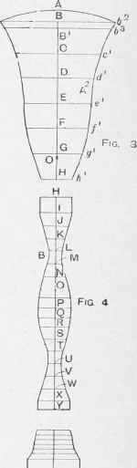
Fig. 5.
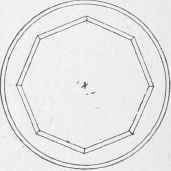
Fig. 6.
Continue to:
My Books

