Condensation. Part 2
Description
This section is from the book "The Engineer's And Mechanic's Encyclopaedia", by Luke Hebert. Also available from Amazon: Engineer's And Mechanic's Encyclopaedia.
Condensation. Part 2

Fig. 1.

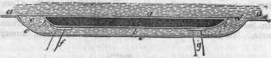
Amongst the first to put in practice this system of condensation in steam vessels was Mr. D. Napier, of Glasgow, who made trial of various arrangements of cooling surfaces, and if he did not completely succeed in removing the evils complained of, he at least greatly reduced the amount of them. The arrangement which he adopted in a small iron vessel, called the Kilmun, deserves notice from its extreme simplicity. The condensers consisted of a shallow iron casing, on each side of the engine-room, built upon the internal surface of the vessel, which thus constituted the outer side of the condenser. The inner side was covered by an iron casing, which communicated with the water outside by two large apertures in the vessel; one at the fore part of the condenser, and the other at the after part. The space between the condenser and the casing being sufficient to allow a free circulation of the water, the condenser was exposed on each side to a current of cold water whenever the vessel was in motion.
The annexed diagram, representing a horizontal section of the condenser, will more fully explain the construction of this ingenious apparatus. a a represents a portion of the side of the vessel, constituting the outer side of the condenser; b the inner side; c a sheet iron casing, which encloses the condenser on the inner side; d the aperture by which the water is admitted between the condenser and casing; e the outlet aperture. The dark space represents the interior of the condenser, to which the steam is conveyed from the slide case by the pipef, attached to the top; and g is a pipe leading from the bottom of the condenser to the air-pump, by which the water and uncondensed vapour are withdrawn. Mr. Howard, of the King and Queen Iron-works, Rotherhithe, endeavoured to combine condensation by injection with surface condensation. The condenser consisted of a cylinder of copper, communicating with the eduction passage, and enclosed within another vessel, through which a current of cold water was maintained by means of pumps worked by the engine.
Within the annular space between the two vessels was placed a worm of thin copper, the upper end of which was connected to a rose head within the condenser, and the lower end of which was connected to a small force-pump, which drew from the lower part of the condenser. The worm being filled with fresh water previous to setting the engine to work, at each stroke of the engine a portion of this water was injected into the condenser amidst the eduction steam, which thereby became condensed; and a portion of the water resulting therefrom was returned to the refrigerating worm by the force-pump, and the remainder forced into the boiler by the feedpump. This plan of condensation was tried on board a government vessel, as also in two other vessels constructed by Mr. Howard, and, we believe, with satisfactory results: but as it formed only an accessory to Mr. Howard's "Vapour Engine," which proved a failure, it shared the rejection of the latter.
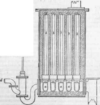
Some years subsequently, Dr. Church obtained a patent for a method of condensation, which was the same in principle, although the arrangements were somewhat different. The opposite figure represents a section of the apparatus, a b c is a vessel called the refrigerator. It is divided into three compartments, placed over the condenser e, the upper one a being connected with the lower one 6 by a series of pipes of small diameter, which occupy the middle portion or cold water cistern c. During the operation of the engine a constant stream of cold water is maintained through this cistern. The chambers a and b being previously filled with distilled water, upon the admission of the steam from the engines into the condenser e by the pipe d, the injection-cockf is opened, and the injection water is distributed in a shower amidst the steam by the rose g, by which the steam is instantly condensed, and the water resulting from the condensation, together with the injection water, is drawn off by the air-pump, and delivered into the compartment a, to be cooled down again by descending through the refrigerating pipes c.
On the top of the chamber a is a small open pipe for the escape of any air given out by the water.
But no person has contributed so much to the introduction of this system of condensation as Mr. S. Hall of Basford, by his various contrivances to meet all the exigencies of the case, by his improvements in the construction of the apparatus, and by his unwearied exertions to demonstrate the superiority of the system, and to procure its general adoption. The following description will serve to give a general idea of his arrangements. The condenser consists of a cast-iron vessel, divided into three compartments by two horizontal plates. Into these plates are secured the ends of a vast number of copper tubes of small diameter, which form a communication between the upper and lower chambers, or compartments, of the condenser. Through the middle compartment, or cold water cistern, a stream of cold water is maintained by a double-acting pump. The upper chamber communicates with the eduction passage, and the lower with the air-pump. The steam from the eduction pipe entering the upper chamber, is instantly dispersed through the condensing tubes; and by its contact with their cold surfaces, is reduced into water, and falls in a shower to the lower compartment; from which it is drawn, together with the air and uncondensed vapour, by the air-pump, The air-pump delivers the water into a hot well, which is closed at top, so that the upper part constitutes an air vessel, and the elasticity of the compressed air forcesthe water into the boiler, through a pipe proceeding from the lower part of the hot well to the feed valves or cocks on the face of the boiler.
Continue to:
My Books

