380. The Hydraulic Flanging Press
Description
This section is from the book "An Elementary Outline Of Mechanical Processes", by G. W. Danforth. Also available from Amazon: An elementary outline of mechanical processes.
380. The Hydraulic Flanging Press
This machine is shown in Fig. 230. It consists of a heavy cast-iron body carrying four hydraulic cylinders, and a suitable table on which work is held steady while being flanged.
The plunger head on the rod A of the outer vertical cylinder clamps the sheet to be flanged by pressing it against the former-block K. The head on the rod B is then forced down against the edge of the plate, turning it down against the right-hand edge of the former-block. The flat end F on the rod C, which is controlled by the horizontal cylinder partly in view, is then forced against the flange to smooth it. The triangular block G serves as a guide to keep B in place as it descends.
The horizontal cylinder on top of the press is rigged merely to lift the heads carried by the vertical cylinders. The pressure in the cylinders A, B and C is admitted from the hydraulic accumulator and released by means of the hand levers on the side of the press. The upper cylinder is under constant pressure and acts similar to a spring.
When the edge of a circular plate is to be flanged, a heavy cast-iron pivot is bolted to the center of the plate and is dropped into a socket on an extension piece bolted to the table of the press. In this way the turning of a flange truly circular is assured.
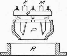
Fig. 231. - Former for Hydraulic Flanging.
When necessary to flange the edges of a circular or an elliptical hole in a plate, the hollow former-block R of Fig. 231 is bolted to the table and the cross head Q is attached to both vertical cylinder rods by the projections K and M. This cross head carries the hollow flanging block P. By means of these fittings the flange entirely around the hole is pressed at one motion.
The degree of heating a plate edge must be carefully judged so that the metal will be pliable, yet not soft enough to be torn away by the downward pull of the flanging head.
Continue to:
My Books

