Telephone Construction. Part 3
Description
This section is from the book "American Library Edition Of Workshop Receipts", by Ernest Spon. Also available from Amazon: American Library Edition Of Workshop Receipts.
Telephone Construction. Part 3
Fro. 112
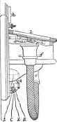
Fig. 113.
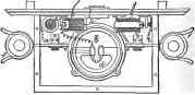
When the plate of the microphone is in the position shown in Fig. 113, so as to close the box, the wire a, Fig. 115, is joined to the wire a, Fig. 114, and the wire 6, Fig. 115, is joined to the wire i, Fig. 114. In constructing the apparatus, a microphone c of any suitable construction (but by preference having at least 6 contact - points) is attached to the upper part of a box, the lower part of which box is provided with a Gower telephone 4, constructed in the form known as the chronometer telephone. This telephone is provided with a bifurcated acoustic or speaking tube, having 2 branches, in order to enable the operotor to listen with both ears if required. Commutators / are provided at the side of the box, for the purpose of interrupting the passage of the current from the battery, and opening the circuit of the call - bells. After working the apparatus, the eitremities of the acoustic tubes a are placed in holders connected with the commutators/, and the circuit is thereby - interrupted. An electric call - bell g it provided underneath the box, and a knob A for working the call bells Is placed at the upper part of the apparatus.
An induction - coil is situated inside the box, and the microphone o and the battery are connected to the primary circuit, whilst the Gower telephone and the line are connected with the secondary circuit. In speaking against the upper part k of the box, winch may be of wood, iron, brass, or other suitable material, and near or upon the under surface of which the microphone is placed either with or without attaching the microphone to the box top directly, the sound - waves from the voice form electrical undule - tions in the primary circuit through the action of the microphone, and these undulations are reproduced in the secondary circuit by induction, and are thus repeated in the Gower telephone at the receiving station. Especial attention is directed to the fact that the microphone in this combination is not necessarily attached to the box top, but that it may be carried upon a framework attached at any point to the combined apparatus. The undulations, however, when so reproduced, are intensified to such an extent by the great power of the magnet in the Gower telephone, that they act upon the microphone in the same case with such effect as to set up corresponding undulations In the primary circuit at the receiving station, and these undulations are again reproduced in the Gower telephone with increased intensity.
Fig. 114.
Moreover, when the diaphragm of the telephone is provided with a vibrating reed x. Fig. 115, as is usual in the Gower telephone, ft is simply necessary to close one of the branches of the acoustic tube, and blow into the other branch, in order to cause the reed to vibrate, and thus produce powerful vibrations of the plate before the magnet. These vibrations not only produce currents in the coils or the poles of the magnet, but also act with great power upon the microphone, the sound being produced In the interior of the tame box, and thus doable the effect of the signal current on the line wire Without exhausting the battery to any greater extent than when (peaking in the usual manner through the apparatus. By employing this combination of magneto - electric and electro - magnetic great power upon what is known as the "Ader" disc, or upon any other suitable receiving instrument at the distant station as well as in the case of ■ system worked with a central office, and any suitable arrangement of the mechanical parte may thus be employed at the receiving station.
It also results from the employment of this combination that a failure of the battery will not stop the commnnica - tion, the Gower telephone being always capable of working the apparatus, whether employed as a receiver or an a transmitter, provided that the wire is not broken, whilst it is also possible, when the Ader signalling apparatus is employed at the central office or other receiving station, to transmit a signal without employing a battery, as in the case of the ordinary Gower telephone. The employment of bifurcated or double acoustic tubes obvintes the necessity for having a separate Instrument as receiver, and thus enables the flexible conducting wire to be dispensed with, which wire constitutes one of the principal objections to the use of telephones in practice.
(5) Calls
(a) This is not so noisy aa bells, yet sufficient for the purpose. Fig. 116: a, tube; b, brass screw, platinum - pointed; c, brass block and platinum reed. On blowing into the month of the tube at a, a musical note is produced by the vibration of the reed c, and the circuit Is interrupted at the point c, the effect of which is that the note Is produced at the distant station with nearly the same force. The effect would be augmented if a small induction - coil were placed with its primary terminals, connected across at zinc line, and the ends of secondary coil joined to zinc proper. The point of the screw may be nearer the end of the reed than.
Fig. 116.

(b) Fig. 117: a, board; b, brass spring fitted with a handle for convenience of shifting; 1, 2, and 3 are the studs, connected as shown. It will be observed that one of the wires from telephone bell and battery is connected to the earth - plate e, or return wire. In the position shown, the telephone is in use; if the spring is moved to No. 3, the bell at the other end of the line (the apparatus is supposed to be in duplicate) will ring, provided the switch is on No. 1 stud. Keep the switch on No. 1 to let the home bell be rung. (Cory.)
Fig. 117
Continue to:
My Books

