Angle Connections
Description
This section is from the book "Do It Yourself With Aluminum. 125 Projects For The Home Craftsman", by G. W. Birdsall. Also available from Amazon: Do It Yourself With Aluminum.
Angle Connections
Cobner Joints In Angles
Figures 4-33 and 4-34 show easily made corner joints in 1/8" x 3/4" x 34" angle. Either bevel ends or overlap ends. Saw off a length of 34" angle for the corner splice in Fig. 4-33. Bend around and overlap vertical leg in Fig. 4-34 to secure joint. Bolt or rivet either joint. Both these designs arc suitable for use where the vertical leg is on either the outside or the inside of the corner.
For 1/16" x 1" x 1" angle, cut a splice plate from the same stock and rivet either inside (Fig. 4-35) or outside the vertical legs. Use two 1/4" x 3/32" rivets on each leg to prevent twisting.
The design of Fig. 4-36 avoids twisting by using a long overlap as shown. For added strength on both joint designs, rivet a flat, triangular gusset plate to the horizontal legs inside the corner as in Fig. 4-37.
Corner Bends In Angles
Notching, then bending, is best way to get angle stock around a corner. That method is usually preferred to making a joint at a corner because there is no interruption of metal in the outer surface. The following instructions are for working 1/16" x 1" x 1" angle: To provide enough metal to make the bend without cracking, always drill a 3/32" hole exactly at the corner, as shown in Fig. 4-37. This hole must be right up against the outer leg of the angle. Then for 90° corners make two 45° cuts into the drilled hole as shown. File sawed edges smooth and straight where best appearance is desired.
Place the unnotched leg of the angle in a mechanic's vise with the point of bend exactly at edge of vise jaws. Now pull the angle around the bend with your hand, lightly tapping the metal at the bend with a wood or rubber mallet as you complete the bend. For an entirely closed notch, use a small steel hammer to work the metal shut as you complete the bend.

This method provides a sharp, clean corner bend with a completely closed notch in the 1/16" x 1" x 1" angle as shown in Fig. 4-38. The added thickness in %" x 3/4" x 3/4" angle necessitates a different method as follows:
Determine the exact position of corner. Then drill two 1/8" diameter holes side by side through the leg to be notched as shown in Fig. 4-39. Saw through center line of holes to make two 45° cuts. Use rat-tail file to remove small point remaining between holes. Clamp in mechanic's vise, and bend, hammering the metal lightly to close the notch as you complete the bend. The two holes blend into one as shown in Fig. 4-40. If, after adjusting lengths as described below, the hole appears egg-shaped or uneven, redrill it to improve its appearance.
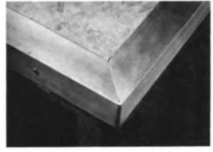
Fig. 4-38.

Fig. 4-39.
Another type of corner bend (Fig. 4-41) can be made in the 1/16" x 1" x 1" angle by drilling a 3/32" hole at the bend point, making a saw cut directly into this hole, then bending the angle, allowing the horizontal members to overlap as shown. Rivet or bolt the overlapping members.
Adjusting Lengths Between Bends
When fitting angles to table tops for trim and for other precise work, it often is desirable to change the distance between two bends slightly. This is easy with the following technique:
Secure the unnotched leg of the section that is too long in a mechanic's vise with a corner about 1/16" from the edge of the vise jaws. Clamp tightly. Then with a lightweight hammer, strike the metal directly on the corner. Being clamped tightly in the vise, the metal can move only toward the open member. As metal flows around this corner under repeated blows, the notch members will slide slightly to accommodate it.
The section of angle can be shortened as much as 1/32" or more by this method. It also works on the 1/8" x 3/4" x 3/4" angle. Redrill the clearance hole if it is distorted.

Fig. 4-40.

Box Framing
The easiest way to construct a box frame is to bend an angle to make a complete loop for the top frame, bend another piece of angle for the bottom frame, and then join the two with vertical posts at the four corners, as shown in Fig. 4-42. Join abutting ends of frames with splice plates. Rivet corner post to top and bottom frames as in close-up diagram (Fig. 4-43). This shows the corner post inside the frames, usually the best way, although it can also be placed outside the frame if desired.

Fitting Angle Around Tube
For certain projects like the stretchers around the lower ends of table legs (Fig. 11-9) one side of 1" angle stock is cut to fit around 34" diameter tube. The best method of accomplishing this is to make the plain bend as detailed in Fig. 4-37. Then after bending and closing the notch, clamp in that position under a drill press and drill the 34" diameter hole exactly in the corner. Or if a drill press is not available, scribe a circle of that size in the corner and cut it out with a scroll saw. Smooth the hole edges with a rattail file.
Figure 4-44 shows another method. First drill the %2" hole exactly at the corner. Mark 45° lines to this hole, and drill two 3/4" holes as shown. Cut out on solid lines, and bend. The two 3/4" holes will fit together to form one. Figure 4-45 shows the completed joint .... 1/16" x 1" x 1" angle around 34" tube. Use self-tapping sheet-metal screws to lock angle to tube.


Continue to:
My Books

