Applications Of Riveted Girderwork In Connection With Water-Tank Construction
Description
This section is from the book "Notes On Construction In Mild Steel", by Henry Fidler. Also available from Amazon: Notes On Construction In Mild Steel.
Applications Of Riveted Girderwork In Connection With Water-Tank Construction
In presenting details of this application of girderwork it has been found advisable to consider at some length (without entering fully upon the important subject of tank construction in general) the details of the tanks themselves, which in this case are of cast iron, as it is hoped that the practical examples described will not be without value to the student.

Fig. 102. Scale ⅜ inch = 1 foot.
Figures 102 to 125 give details of a class of cast-iron tank frequently found in the upper portions of engine houses for pumping machinery, hydraulic accumulators, or other central power stations, and serving as storage tanks for steam or hydraulic machinery, fire purposes, or the like. They not unfrequently form the whole or a portion of the roof in such structures, and where, as in the latter case, they are associated with ordinary roofing details, it is frequently necessary to adopt certain special methods of completing the weathertightness of the whole arrangement.
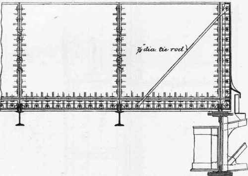
Fig. 103. Scale ⅜ inch = 1 foot.
In buildings of any considerable architectural importance it may be desirable to conceal the tank behind the parapet or upper portion of the walls of the main building. This leads to a diminution, other things being equal, of the capacity of the tank, as it is desirable to leave sufficient space between the sides of the tank and the enclosing walls for the purpose of examination, painting, or repairs.
On the other hand, the tank is frequently open to view, and may be treated, as far as possible, as an architectural member of the design, although it must be confessed that the ordinary methods of embellishment are not usually remarkable for their artistic success.

Fig. 104. Scale ¾ inch = 1 foot.
Figures 102, 103, and 104 give part longitudinal and transverse sections of the tank.
Figure 104 shows that side of the tank next to the enclosing parapet wall of the main building. Fig. 102 shows the side of tank next to the roofing and roof principal of special construction referred to in Chapter V (Roof Construction In Mild Steel And Iron)., p. 301.
The tank consists of cast-iron flanged plates, forming the bottom and sides. The bottom plates in the tank under consideration are of the dimensions shown in length and width, these dimensions being obtained by the setting out of the girderwork carrying the tank, and are probably about as large as plates of this kind should be made, having regard to the head of water supported (only about 4 feet 6 inches in this case), and to the necessity of uniformity of thickness in the metal, avoidance of flaws, etc.

Fig. 106. Scale ¾ inch = 1 foot.

Fig. 105. Scale ¾ inch = 1 foot.
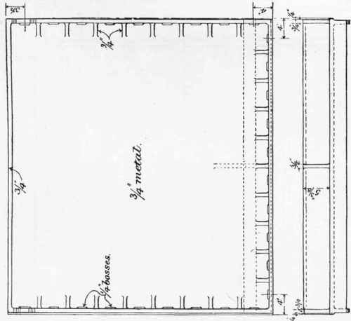
Fig. 108. Scale ¾ inch = 1 foot.
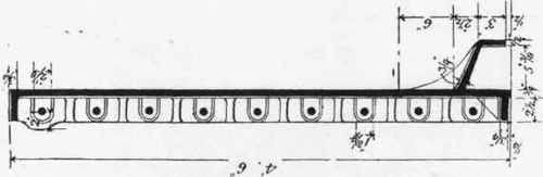
Fig. 107. Scale ¾ inch = 1 foot.
Bottom and side plates are shown in Figs. 105 to 108.
The side plates are of similar lengths to the bottom plates, and 4 feet 6 inches in height. The thickness of metal in bottom and side plates is ⅞ inch and ¾ inch respectively; the actual thickness will be governed by the depth of water carried, but the requirements of the foundry will necessitate a limit of thinness beyond which the risk of inequality of metal will be run.
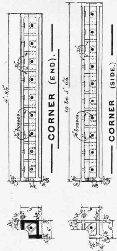
Fig. 109. Scale ¾ inch = 1 foot.
The side plates are connected with the bottom plates by the angle pieces shown in Figs. 102, 103, 104, and on a larger scale in Fig. 109. The angle pieces in this case are shown with a square corner in the angle. This form, which offers a certain simplicity in the pattern-making, would not be a good one for heavier pressures of water, and an angle or connecting piece having a circular quadrant section is frequently used, in accordance with the well-known principle regulating the best form of cast-iron construction under heavy pressures, such, for example, as the bottoms of hydraulic rams. Such considerations, however, are not to the point in such a case as the present, where the head of water is inconsiderable.

Fig. 110. Scale ⅜ inch = 1 foot.
The tank is divided into two halves by a partition of plates similar to the side plates, as shown in Figs. 110 and 111. This division serves the purpose of providing a reserve of water storage when one-half of the tank is laid dry for cleaning or repairs, but it sometimes implies the use of a double set of supply, outlet, and overflow pipes, while the partition itself must be capable of resisting water pressure on alternate sides. The connection of the division plates with the sides and bottom is formed by a double angle piece, cast in one, as shown in Figs. 110 and 111. The junction at the vertical corners of the tank are also formed by single angle pieces, as shown in plan in Fig. 112.
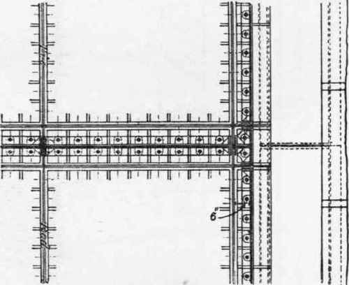
Fig. 111. Scale ⅜ inch = 1 foot.
The whole of the bottom and side plates are provided with flanges round their edges, as shown in the illustrations, of sufficient depth (in this case 2½ inches) to accommodate the size of the bolts used in connection. All the meeting surfaces of these flanges are, in good work, machined where they are in contact, a chipping or planing fillet being provided for that purpose, in such wise that when fitted together a caulking space of about ½ inch in width is left between the flanges, which space is filled up with iron cement to form a perfectly watertight joint. The flanges are stiffened by a gusset piece between every bolt, the bolt-holes being cored out to receive galvanized bolts. Occasionally the holes are left square, and the bolts provided with square necks. Upon the efficiency of the caulked cement joint the proper Watertightness of the tank mainly depends.

Fig. 112. Scale ⅜ inch = 1 foot.
Continue to:
My Books

