Applications Of Riveted Girderwork In Connection With Water-Tank Construction. Continued
Description
This section is from the book "Notes On Construction In Mild Steel", by Henry Fidler. Also available from Amazon: Notes On Construction In Mild Steel.
Applications Of Riveted Girderwork In Connection With Water-Tank Construction. Continued
It will be observed that, in the tank under consideration, the flanges are turned inside the tank, and not outwards. This is not an invariable rule, and there are arguments for and against the practice. As regards the strength of the plates, the method shown has the advantage, for experiment has shown that a cast-iron tee-shaped section loaded transversely is stronger with the table downwards than upwards, in accordance with the laws governing the relative resistances in compression and tension of cast-iron sections. On the other hand, the use of the flange turned inwards converts the bottom of the tank into a number of independent pockets without drainage from one to the other, when the tank is laid dry for cleaning purposes. This disadvantage can, however, be met, if necessary, by lining the tank bottom to the level of the top of the flange with Portland cement mortar.
Fig. 113.

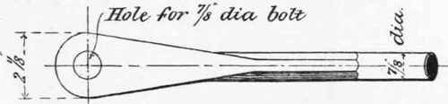
Fig. 114. Scale 3 inches = 1 foot.
The necessary resistance of the side plates to the bursting pressure of the water is provided in the case under consideration by wrought-iron heavily-galvanized tie-rods, placed at an angle of about 45°, and connecting the top of the side plates with the flanges of the bottom plates. One such rod is provided at every joint in the side, end, and partition plates, as shown in Figs. 102,104, and 110. These rods are forged with jaws of sufficient width to embrace the pair of flanges at each joint, as shown in Figs. 113 and 114, which show the fork or jaw in plan and elevation. They are bolted at both ends to the flanges of the side and bottom plates, a convenience afforded by the method of turning the flanges inwards. The connection of the tie-rod to the top of the side plates is shown in Fig. 115. The side plates are further stiffened by a horizontal flange on the upper edge, as shown in Figs. 105 and 115.
In deeper tanks than that shown, the rods are frequently carried horizontally across from one side to the other, at intervals apart depending upon the pressures. In all cases of cast-iron tanks these tie-rods are of vital importance to the security of the tank, and hardly too much attention can be paid to their design, fitting, and subsequent maintenance.

Fig. 115. Scale 3 inches = 1 foot.
The total weight of such a tank as that above described, when filled with water, being considerable, careful consideration of the supporting framework of girders is desirable. This framework is shown in Figs. 102,103,104,110, and consists of main riveted plate girders carrying cross riveted plate girders, which last support rolled joists, the whole being of mild steel. The general arrangement of this girderwork is shown in the figures. The main girders are supported at one end upon the main walls of the building, of which the tank forms a portion of the roof, the other end being carried upon a steel riveted column, which is described in Chapter IV (On The Practical Design Of Columns And Struts)., p. 231. The connection of the main girders over the column is shown in Fig. 110. The cross girders are supported by the main girders, and their connections are shown in sectional plan in Fig. 110, and in elevation in Fig. 102. The depths of the main and cross girders are so regulated that the upper surfaces of the rolled joists which rest upon the latter are in the same horizontal plane as the upper surface of the top flange of the main girder. The cross-section of the main girder at the centre is shown in Fig. 116, and at the end in Fig. 117. It will be observed that, as the number of plates in the upper flange fall off towards the ends, the level is preserved by means of the 8½" X ⅝" packing strips, shown in Fig. 117, forming together, with the upper surfaces as aforesaid of the rolled joists, which are carefully straightened and levelled in the press, the plane surface upon which the cast-iron bottom plates of the tank are bedded, the actual contact being made by the 1-inch deep fillets cast on the underside of the plates, as shown in Figs. 103 and 116.

Fig. 116. Scale 1 inch = 1 foot.

Fig. 117.
Scale 1 inch = 1 foot.

Fig. 119. Scale 1 inch = 1 foot.
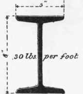
Fig. 118. Scale 1½ inch = 1 foot.
These fillets are chipped or machined until true and even contact is obtained.

Fig. 120. Scale ⅜ inch = 1 foot.
The cross-section of the rolled joist is shown in Fig. 118, and that of the cross girder at the centre in Fig. 119.
The bearing of the main girder on the wall is shown in Fig. 104 in elevation, and in sectional plan in Fig. 120. The bearing on the column is shown in Fig. 110. The bearings of the rolled joists on the wall are shown in Figs. 121 and 122.
The object sought to be obtained in the arrangement of girderwork above described is to prepare a practically rigid and even bed for a tank constructed of a material (cast iron) not well adapted to resist cross strains arising from excessive or unequal deflection, and in which it is of prime importance to preserve the joints from starting and becoming leaky.
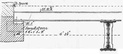
Fig. 121. Scale ⅜ inch = 1 foot.
To prevent undue deflection or alteration in shape arising from the difference between a full and empty tank, it is desirable either to give the supporting girders an ample proportion of depth to span, if space will allow, or otherwise to keep the working stresses low, by extra metal in the flanges.
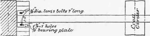
Fig. 122. Scale ⅜ inch = 1 foot.
It has been above remarked that in cases where tanks of this class form a portion of the roof of the building, and are associated with ordinary roofing details, some special arrangement for forming a weathertight connection between the two becomes necessary.
Certain methods by which this may be effected are illustrated in Figs. 123, 124, and 125.
In Fig. 102 the tank is shown abutting on a roof principal of the type described in Chapter V (Roof Construction In Mild Steel And Iron)., p. 302, carrying a cast-iron gutter shown in detail in Fig. 272; and it is necessary to form a watertight connection between this gutter and the side of the tank. A similar detail occurs in Fig. 104, where a gutter runs round between the tank and the parapet wall. In both these cases the object desired is obtained by the use of the special connection shown to a larger scale in Fig. 123, which consists of a weathering flange cast on the outside of the side plates of the tank in the position shown, and having a vertical lip or feather overlapping the gutter, which is tucked in under the flange, as shown. All direct attachment between the tank and the gutter is avoided, either being left free to expand or contract independently of the other. The gutter work is carried completely round the tank as shown in plan in Fig. 112, which also shows the arrangement of the weathering flange at the corners of the tank.

Fig. 123.
Other methods of attaining the same end are shown in Figs. 124 and 125.
In Fig. 124 a gangway is provided between the tank and the parapet wall for painting or repairs, floored as shown, and covered with a small lean-to roof of zinc and boarding, draining direct into the tank.

Fig. 124. Scale ⅜ inch = 1 foot.
In Fig. 125 connection is made with the gutter of a neighbouring roof in the manner shown, a lining of boarding covered with zinc being attached to the tank and the gutter in such a way as to prevent wet from getting down into the building.
All the details connected with the hydraulic pipework required in connection with such tanks as those above described cannot here be described. In general three sets of pipes - supply, discharge, and overflow - will be required, and it is usual to effect the junction of these pipes with the tank by means of special provision in one or more of the bottom or side plates, these being especially stiffened up for that purpose. But in cases where lofty stacks or considerable lengths of pipes are required, the expansion and contraction of such pipes due to temperature changes should be borne in mind, and not allowed to visit themselves upon the connections to the plates of the tank, with alternating stresses. Automatic or electric tell-tales of water-level will also be required.
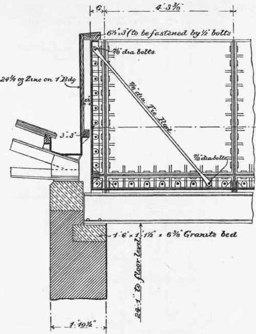
Fig. 125. Scale ⅜ inch = 1 foot.
Continue to:
My Books

