Caissons. Part 2
Description
This section is from the book "Notes On Construction In Mild Steel", by Henry Fidler. Also available from Amazon: Notes On Construction In Mild Steel.
Caissons. Part 2
The stringers supporting the frames in the central well, compartments 7, 8, and 9, were not, for economical reasons, designed to resist the full collapsing pressure of the water which came upon them in process of pumping out of the compartments, and they were accordingly strengthened by temporary timber struts of pitch pine, 14 inches square, arranged as shown in plan, Fig. 389, and arranged in tiers as shown in Figs. 388 and 390. These struts were removed as the concreting of the structure was brought up.

Fig. 391. Scale ¼ inch = 1 foot.
The upper portion of the caisson was surmounted by portable steel bulwarks of 5/16-inch plate stiffened with angles and strutted internally with timber, as shown in Figs. 388 and 390, this strutting being so arranged as to form a platform on top for the temporary work connected with the flotation, sinking, and concreting of the structure.
Six sluice valves, 12 inches in diameter, lined with gun metal and tested to 150 lbs. pressure, were supplied, one to each subdivision of the end watertight compartments, Nos. 1, 2, 3,4,5, and 6.
These valves were worked, as shown, from the upper platform, and were for the purpose of admitting water to the end compartments aforesaid.
Mooring rings were attached to the caisson at convenient places, and the sloping ends were provided outside the skin plating with angle irons riveted to the plating and running vertically up the slope, to form a key with the first layer of concrete blocks laid against the slope, and moulded with corresponding grooves in the blocks, to minimise the risk of the first row or rows of blocks being shifted off the face of the caisson by sea stroke until they received the full weight of the succeeding tiers.
The caisson was constructed and put together in the building-yard at home, and was subsequently taken to pieces and shipped to the site of the works, there to be re-erected, riveted, and launched, completed in the water, floated out to the site of the breakwater, and sunk.
Local conditions connected with the site of launching and depth of water available, made it desirable that the launching draughts should not exceed 2 feet 1½ inch forward, and 4 feet 6½ inches aft, and to obtain these conditions the caisson was launched in an incomplete state, with only so much of the framework and skin plating erected as was compatible with the above conditions.
The caisson was launched end on, in preference to broadside on, the bottom of the central well compartments being temporarily decked over with 4-inch planking of sufficient Watertightness to serve for launching purposes. This was subsequently removed when the caisson had been towed into sufficiently deep water.
A section of the launching ways is shown in Fig. 391, the ways being laid with a declivity commencing with 9/16 inch per foot, and terminating with 15/16 inch per foot at low water, the declivity of the caisson itself being 9/16 inch per foot.
A minimum depth of water of 11 feet at low water, extending outwards for about 60 feet beyond the end of the ways, with a width of 70 feet, sufficed for launching purposes, the launch being successfully effected.
The subsequent process of erection and completion of the caisson in the water was but a repetition of the process of building up successive additions of steel-work in framing and skin plating, and the gradual loading up of ballast, until the entire structure, including all temporary timber work and other temporary appliances, was completed, and sunk to its final draught on an even keel of 32 feet, as designed.
In view of the sea risks to be encountered during all the stages subsequent to the launch, of completion in the water, floating out to the site, and final sinking in place, it was deemed desirable that a large amount of transverse stability when afloat should be maintained.
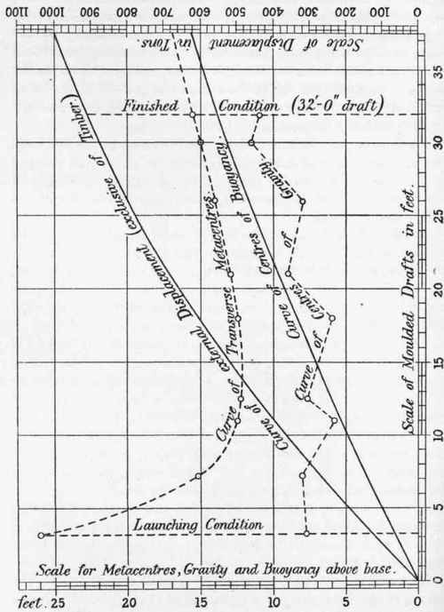
Fig. 392.
This was secured by the ballast stowed upon the floor, and between the floor girders, of compartments 1 to 6 inclusive. This ballast consisted for the most part of burr concrete, composed of steel "burrs" or punchings grouted in with Portland cement mortar, and supplemented with ordinary concrete ballast. By this means a large metacentric height was maintained at all stages of construction, as shown in Fig. 392, which gives the curves of centres of buoyancy and gravity, metacentres, and displacement from the launching condition to that of final flotation and draught previous to sinking.
A summary of the weights at launching and at the finished draught of 32 feet is given in the following table:-
Launching condition. Tons. | Final condition. | |
Net steelwork | 219.87 | 383.66 |
5.34 | 9.31 | |
Paint ... ... ... ••• | 2.37 | 4.14 |
Timber | 20.68 | 90.06 |
Bolts and plates for timbers | 0.34 | 2.89 |
Burr concrete | 33.00 | 412.50 |
Ordinary concrete ... | • • • | 58.70 |
Sluices and mooring rings | • • • | 2.99 |
Total weight | 281.60 | 964.25 |
Draught forward ... | 2' 1½" | 32' 0" |
Draught aft... | 4' 6½" | 32' 0" |
The conditions of stability at the final condition (32 feet draught) were as follows : -
Centre of gravity | 11.12 feet above base |
Transverse metacentre | 15.60 |
Centre of buoyancy | 13.80 |
Transverse G.M. | 4.48 feet. |
The burr concrete was about 2 feet thick over the floor, and the ordinary concrete placed above was about 9 inches thick.
The burr concrete,1 412.5 tons in weight, was composed of 370 tons of punchings and 42.5 tons of Portland cement and sand, the mixture weighing about 350 lbs. per cubic foot. Experiments made on the weight of concrete used in filling the caisson gave the following results:-
1 For further remarks on Burr concrete, see p. 402.
1 Portland cement, 1½ sand, 5 limestone broken to pass through an l½-inch ring, weighed 155 lbs. per cubic foot = about 14½ cubic feet per ton, the voids in the limestone being about 44 per cent, and those in the sand 30 per cent.
A concrete of 1 Portland cement, 2 sand, and 5 broken stone, gave nearly the same results, weighing 157 lbs. per cubic foot = say, 141/3 cubic feet per ton.
The caisson up to this point has been considered simply as a riveted steel structure, and further reference to its subsequent history and the ultimate use to which it was put might be regarded as outside the scope of these notes, if it were not that the subsequent operations explain certain peculiarities in the design. These, then, will be briefly alluded to.
Continue to:
My Books

