Caissons. Part 5
Description
This section is from the book "Notes On Construction In Mild Steel", by Henry Fidler. Also available from Amazon: Notes On Construction In Mild Steel.
Caissons. Part 5
These details show also the mode of connection of the timber keels and stems with the framework and skin plating of the body of the caisson, to resist the severe shearing (or combination of shearing and bending) stresses which take place at this point. The method shown in Figs. 394, 395 has been successful in caissons having a total area of entrance up to 3500 or 3800 square feet.

Fig. 394. Scale ½ inch = 1 foot.

Fig. 395. Scale ½ inch = 1 foot.
Beyond this amount of area, and for greater water pressures, it has been deemed advisable to adopt the type of construction shown in Fig. 396, showing a stronger method of connection with the caisson body; but this type of keel demands a groove of greater width, as shown in the figure. It has been applied to dock entrances having a total area of opening of 5163 square feet.
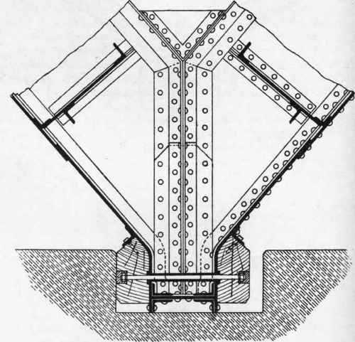
Fig. 396. Scale ½ inch = 1 foot.
The arrangement of timber keel for a sliding caisson is shown in Fig. 397, which gives the arrangement of the internal steelwork at this point, and shows the fine axed granite sliding way upon which the caisson moves, and the patent axed granite stop which forms the watertight seal with the timber keel.
In the above examples the net width of the surfaces in contact, after allowing for roundings or chamfers, is from 11 to 13 inches, and this amount, under the severe pressures experienced, is found to give a satisfactory watertight joint.
The pressures to be sustained by the timber require a hard wood, and the exposure to the ravages of worm, a wood as little susceptible as possible to these attacks, consequently the timber employed is very frequently greenheart, which also yields the required scantlings without difficulty. The timber used should be of the best quality, well seasoned, in long lengths, worked with square butts properly shifted with regard to joints in steelwork. The outer faces of the keels and stems should be planed to true surfaces to meet the masonry faces with which they are in contact (in some cases the centre of the contact-face of the timber has been left a trifle proud).

Fig. 397. Scale ½ inch = 1 foot.
The inner surfaces are carefully scribed over all angles or covers in the steelwork, and well bedded on canvas soaked in red lead paint so as to form a watertight joint.
The timbers are secured to the steelwork by galvanized bolts and coach screws, as shown in the details, the bolts, in the case of the floating caissons, passing through steel ferrules, and in the sliding caissons through the angle steels arranged to take the keel, as shown in Fig. 397. The heads and nuts of the bolts in the keels and stems of floating caissons are sunk into the woodwork, as shown, and covered with timber plugs set in marine glue pitch, the voids round heads and nuts being filled with pitch and sand cement.
The edges of the keels and stems are chamfered, as shown, to avoid splintering due to blows or rubbing against the masonry. The chamfers on the timber and the roundings on the masonry also facilitate the operations of removal and replacing of the caisson.
The details of the stems and keels have thus far been considered as a preliminary to the further stage of the design, viz. the question of the transverse strength of the entire caisson against the maximum water pressure on one side only.
The total amount of the reactions to be supplied by the pressure of the surfaces of the stems and keels is, of course, known, being equal to the total water pressure. But the precise value of the distribution of these reactions over each unit of the entire area of the surfaces in contact is not so easily determined. Assumptions as to distribution of stress may be made, for example, which would lead to the conclusion that the larger portion of the reaction was supplied by the sides of the dock entrance, leaving but little to come upon the lower sill; or, contrariwise, the sill might be supposed to be doing the bulk of the duty, leaving little for the sides, neither proposition being probably quite correct.
If the intensity of pressure at all points round the superficies of sides and bottom keels could be experimentally determined, the calculation of stresses would be simple; but, so far as the writer is aware, this has not yet been ascertained.
The solution is probably to be found in the elastic deformation of the entire structure, where the stiffness of both longitudinal and vertical planes of girders is taken into account, and the distribution of stress is no doubt largely ruled by the rigidity of the principal planes of horizontal girders, which are the upper and lower decks of the air chambers in the types of caissons we are now considering.
These decks having to be watertight are plated, and thus constitute plate-web horizontal girders of great depth (in most cases) in proportion to their span, and having a corresponding rigidity, or small deflection under load.
But the positions of these decks is governed by the dimensions and position of the air chamber, and these latter are determined by considerations quite apart from those governing transverse strength, being ruled by the required buoyancies, and the influences of tidal levels, which will vary with every port.
The usual assumptions, though possibly devoid of mathematical refinements, of considering the entire structure as consisting of so many horizontal girders, each sustaining its proportion of water pressure according to the area exposed and the hydraulic depth, and assisted (where the internal arrangements permit) by other vertical girders crossing the former at right angles, are found to yield practically reliable and safe results, and at least indicate one mode of resistance which must be overcome before final rupture can take place.
By whatever mode of analysis the stresses in the entire structure may have been arrived at, the practical designer will consider the effects of corrosion upon immersed steelwork and the minimum scantlings which should be allowed.
Continue to:
My Books

