On The Practical Design Of Columns And Struts. Part 14
Description
This section is from the book "Notes On Construction In Mild Steel", by Henry Fidler. Also available from Amazon: Notes On Construction In Mild Steel.
On The Practical Design Of Columns And Struts. Part 14
It forms one of a row of columns dividing two adjacent bays of an extensive range of factories, boiler-shops, etc., the bay on one hand having a high-level traveller road, with high-level roof, and on the other hand a low-level traveller road, with low-level roof. Together with the provision for these traveller and roof loads a system of bracing is also attached for the purpose of carrying the various ranges of main and countershafting, with electric motors attached to the column, "required for the varied machine tools to be used in the shops. The variety of loading and of detail of connection thus required rendered the design of these columns somewhat complex, and the results are not without their value to the student. The general arrangement of the columns, and of the traveller girders, roof girders and roof principals asso-ciated with them, is shown in Figs. 216, 217, the bracing for countershafting, which supplied longitudinal stiffness to the rows of columns, being omitted for the sake of clearness.
Fig. 218 is a front elevation and Fig. 219 a side elevation of the base of the column. A plan of the base looking down is given in Fig. 220. It will be observed that the column is held down by eight foundation bolts, the details of which are shown in Fig. 221 and to which further reference will be made.
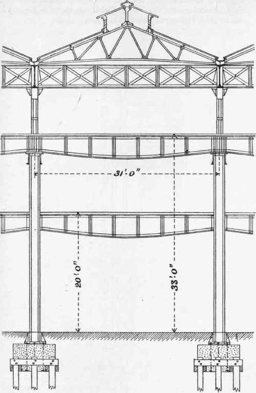
Fig. 216 (Scale 1 inch = 10 feet).

Fig. 217 (Scale 1 inch - 10 feet;.
A longitudinal section of the base is also shown in Fig. 222.
The normal section of the lower portion of the column is given in Fig 223, from which it will be seen that the weight-bearing section consists of two girder-shaped riveted sections, each consisting of a solid web 20" X ¾", four angles 3¾" X 3½" X ½", and two plates 8" X ½". The sections are prevented from twisting by a braced arrangement of flat bars 3" X ⅝", arranged as shown, and spaced at intervals up the column, while the pair of girder sections are united by a latticed web of angle irons riveted to the back of the girder webs as shown in Fig. 219, thereby converting the pairs of vertical columns into one braced vertical cantilever, capable of resisting transverse flexure, and with a very large moment of inertia in the plane of the latticed web; while in a plane at right angles thereto, and in the longitudinal axis of the traveller roads, the girder sections constituting the columns have each a large resistance to flexure in that plane.
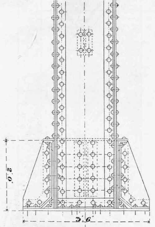
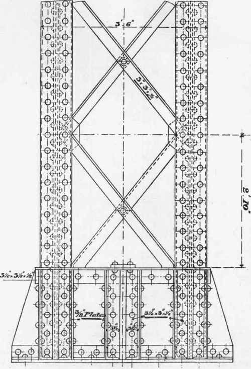
Fig. 219. Scale ¾ inch = 1 foot.
This lower section of the column is continued up to the level of the lower traveller road, provision for which is made as shown in Fig. 224, one girder section being stopped off to carry the lower traveller girder, while the other girder section is continued up unbroken to carry the higher traveller as shown in Figs. 217, 225. It will be seen in Fig. 224 that at the level of the lower traveller seating a new vertical member commences, intended to carry the roof loading above. The base of this roof column is arranged to rest upon the arrangement of plates and angles shown in Fig. 224, by which means the roof load is divided between the twin girder sections of the lower portion of the column. Referring again to Fig. 225, we see that while the column section is stopped at the level of the upper traveller road, the roof column is continued upwards to the summit of the entire column, the total height from the under side of the column being 46 feet 5 inches. The section of the column between the levels of the lower and upper traveller ways is shown in Fig. 230.

Fig. 220. Scale ¾ inch = 1 foot.

Fig. 221. Scale ¾ inch = 1 foot.
The student will observe that the clearance between the faces of columns and the centre line of traveller rail is in this case 11 inches, and he will be in a position to appreciate the influence which this dimension has on the arrangement of details in cases of this kind.
Fig. 226 is a sectional plan on line FF at the level of the lower traveller girder seating shown in elevation in Fig. 224, while Fig. 227 is a section on GG, Fig. 224. Fig. 228 is a section through DD (Fig. 225), and Fig. 229 is a section at CC, looking down upon the seating of the upper traveller girder.

Fig. 222. Scale ¾ inch = 1 foot.
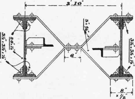
Fig. 223. Scale ¾ inch = 1 foot.
The uppermost portion of the column above the upper traveller road, carrying the lattice roof girder, has sections, which are shown in Figs. 231 and 232, while the detail of the bolted connection between column and roof girders is shown in Figs. 85, 86. The details of the girders themselves are alluded to, together with those of the roof principals which they support, in Chaps. III. and V., pp. 149 and 313.

Fig. 224. Scale ¾ inch = 1 foot.
The general question of foundations is not one which comes within the immediate scope of these notes, but a few remarks upon the nature of the foundations required for the column above described may not be inappropriate.
The column in question was built upon made ground, and experimental tests of its weight-bearing capacity showed that the load to be imposed could not be carried by the bare soil without risk of an amount of settlement which might prove injurious to the traveller roads and the main and countershafting. Piled foundations were therefore provided for the column bases in the manner indicated in Figs. 233, 234 and 235, in front and side elevation and plan.

Fig. 225. Scale ¾ inch = 1 foot.
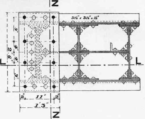
Fig. 226. Scale ¾ inch = 1 foot.
A group of eight piles of whole timber driven down to the solid is connected at the top by a grillage of half-timber sills bolted to the piles as shown, the whole being capped by a massive bed of Portland cement concrete, with carefully levelled top surface, upon which the bases of the columns shown in Fig. 216 were planted.

Fig. 227. Scale ¾ inch = 1 foot.
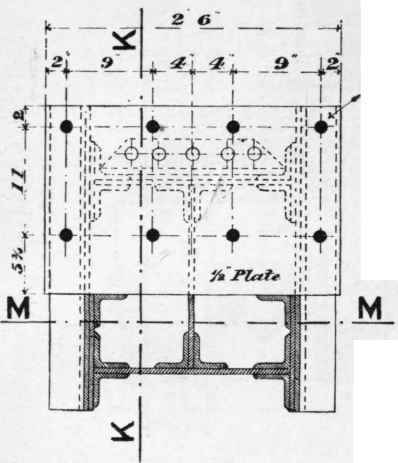
Fig. 229. Scale ¾ inch = 1 foot.

Fig. 228. Scale ¾ inch = 1 foot.
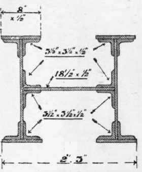
Fig. 230. Scale ¾ inch = 1 foot..

Fig. 231. Scale ¾ inch = 1 foot.

Fig. 232. Scale ¾ inch = 1 foot.
Continue to:
My Books

