On The Practical Design Of Columns And Struts. Part 6
Description
This section is from the book "Notes On Construction In Mild Steel", by Henry Fidler. Also available from Amazon: Notes On Construction In Mild Steel.
On The Practical Design Of Columns And Struts. Part 6
The loss of strength produced by slight eccentricity of loading also becomes evident in two tests; an angle, 2" x 2" x 5/16", 8 feet 3⅛ inches long, properly centred, with 1-inch ball and socket ends, failed at 3.16 tons per square inch; improperly centred, it failed at 1.77 tons per square inch. Again, an angle, 1" x 1" X ⅛", 5 feet 3 inches long, with 1-inch ball and socket, properly centred, failed at 2'58 tons per square inch; a similar bar, slightly out of centre, failed at 1.30 tons per square inch.
Considerable diversity of results is apparent in the hinged-ended specimens, possibly due to varying frictional resistances between the ball and socket, or pin and bearing, and the results are best expressed by an area, rather than a mean line.
The round-ended specimens were arranged with a semi-spherical ball-bearing on a flat plate. Frictional resistances may be assumed to have been absent in this case, and the ends being free to turn upon their bearings, the general results give a somewhat more regular mean line than those of the hinged-ended struts. The line lies, however, obviously along the lower fringe of the hinged-ended area.
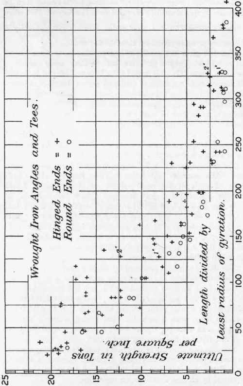
Fig. 130.
Fig. 131 gives the results of compressive tests upon wrought-iron flat-ended channels, joists, welded tubes, and Zed columns. The channels ranged from 2 inches to 12 inches in depth, and from 6 inches to 15 feet in length. The beams ranged from 4 inches to 15 inches in depth, and from 6 feet 6 inches to 22 feet in length.
The tubes were 2.37 and 2.87 inches in outer diameter, and from 3 feet 5 inches to 15 feet in length.
The results of similar sections, but hinged-ended, are shown in Fig. 132. In this series, the influence exerted upon the ultimate strength by the precise conditions of the "hinged-end" are well shown. Thus a welded tube, 3.5 inches external diameter, 15 feet in length, did not fail at 10.5 tons per square inch with a 2-inch pin end, but, with 2-inch ball and socket, failure took place at 6.3 tons per square inch, and with 2-inch ball and plate (round-ended, with practically no frictional resistance) at 5.0 tons per square inch. The result of eccentricity of loading is also shown by a tube of the same diameter and length, with 2-inch pin, set one-tenth of an inch out of centre, which failed at 8.4 tons per square inch.
The quality of wrought-iron used by Mr. Christie in the foregoing tests was as follows: ultimate breaking stress in tension = 21.8 tons per square inch; elastic limit = 14.3 tons; elongation in 8 inches = 18 per cent.
Among the flat-ended specimens plotted in Fig. 131 are shown the results of tests on Z columns with one lattice web carried out by Mr. C. L. Strobel.1 These tests were fifteen in number, and the section of the column was of the'type shown in Fig. 168, consisting of four Z irons, 2½" x 3" x 2 ½" x 5/16" connected by a single lattice web. The lengths of the columns ranged from 10 feet 11¼ inches to 28 feet. The columns were tested horizontally, the lattice web being in a vertical plane. The ends abutted squarely against the castings of the testing machine, without the interposition of shoes, and the mode of failure was uniformly the same, by flexure in the direction of the least radius of gyration, in conformity with theory.
1 Transactions of the American Society of Civil Engineers, vol. xviii.
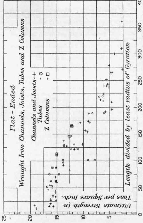
Fig. 131.
The section appears to yield good results, having regard to its simplicity of construction and accessibility for painting. Tensile tests of the iron used in the Z sections gave an ultimate tensile strength of from 22.0 tons to 24'0 tons per square inch, with an elongation of from 11'3 to 22'7 per cent.
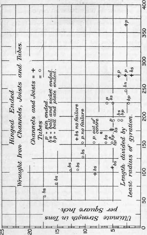
Fig. 132.
In Fig. 133 are plotted the results of tests upon pin-ended lattice columns of the Detroit Bridge and Iron Company, made at Watertown Arsenal.1
These columns were of the type section shown in Fig. 150, consisting of two channel bars, connected together with a double web of lattice bracing. The channels were of sections 6 inches, 8 inches, 10 inches, and 12 inches wide, with flanges of from 1¾ inch to 2½ inches deep. The channels were spaced from 6 inches to 8 inches apart, back to back, strengthened with reinforcing plates at the ends to provide bearing for the pin connections, the pins being 3 inches and 3 ½ inches diameter. The columns failed usually by deflection in the direction of the least radius of gyration.
It will be observed from the figure that 3-inch diameter pins give lower results than 3½-inch diameter, a result in accordance with the tests on 3-inch rectangular bars with pin ends, described on p. 186.
Fig. 134 gives the results in graphic form of Mr. Christie's experiments2 on flat-ended angles of mild steel, which were carried out under similar conditions to those on wrought iron previously described. The steel employed had an average carbon content of about 0.12 per cent., with an ultimate tensile resistance of about 28.3 tons per square inch, and an ultimate elongation of about 23.6 per cent, in 8 inches.
Fig. 135 gives the results of similar experiments on flat-ended angles of hard steel, having an average carbon content of 0.36 per cent., and an ultimate tensile resistance of about 45 tons per square inch, and an ultimate elongation of 17½ per cent, in 8 inches.
Continue to:
My Books

