The Use Of Mild Steel And Iron In Marine Engineering. Part 5
Description
This section is from the book "Notes On Construction In Mild Steel", by Henry Fidler. Also available from Amazon: Notes On Construction In Mild Steel.
The Use Of Mild Steel And Iron In Marine Engineering. Part 5
The main girder connecting the tops of the cylinders is of a heavy box-girder type, and is shown in section in Fig. 360. Cross girders, of which the end of one next the main girder is seen in Fig. 360, carry the decking, which consists of trough flooring plates, as shown, covered with asphalte, and supporting ballast filling upon which the sleepers of sundry lines and crossings are laid, these latter serving the purpose of railway traffic between the jetty and the mainland.

Fig. 353. Scale ¾ inch = 1 foot.

Fig. 354. Scale ¾ inch = 1 foot.
As the main girder flanges are 3 feet in width, while the cylinder below is 7 feet in diameter with a capping 8 feet diameter, the curb or coping line of the jetty is brought forward, so as to be flush with the cylinder cap below, in the manner shown in Fig. 360, riveted steel brackets being attached to the box girder at intervals, supporting a capping of heavy timbers, as shown.
The box girders are of dimensions sufficient to enable painting to be done inside, and means of access are provided.
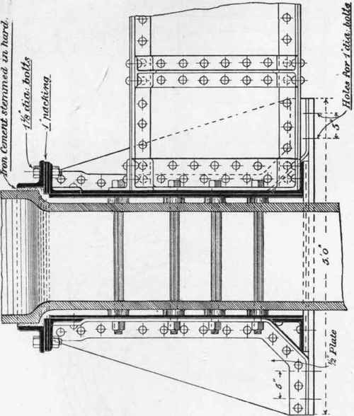
The attachment of a cross girder to the main box girder in rear of the latter is shown in Fig. 361.
The attachment of the bollards in this structure is a detail of importance, and is of more complex type than the single concrete foundation which can be employed under other conditions. It is shown in Figs. 359, 362, and 363, the bollard, of special section, being inserted between the webs of main box girders, as shown in Fig. 363, and carried down below the seatings of those girders into the concrete filling of the cylinder below, the pull on the bollard being further resisted by diagonal ties carried back to the wall behind, the whole being intended to resist the pull of hawser of a heavy vessel.

Fig. 355. Scale ¾ inch = 1 foot.
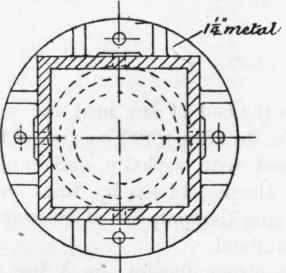
Fig. 356. Scale ¾ inch = 1 foot.
The cylinders are of massive construction, and are spaced, as before stated, about 60 feet apart, longitudinally, in a single row. The upper portion of the cylinder, 7 feet in diameter, is shown in Fig. 358, cast in complete rings, 1½ inch thick, and connected by flanged joints with 1¼-inch bolts through drilled holes. Cast holes are frequently used in this class of work, but holes drilled to a templet are far more satisfactory, and secure complete interchangeability of parts. The advantages gained in this respect in erection counterbalance the additional cost. The meeting surfaces of the flanges are machined all over, it being virtually no more costly than the machining of separate strips. Watertightness during the process of construction and sinking is thus attained, assisted by the use of canvas and red lead jointing material, or by the insertion of india-rubber cord flattened out by the squeeze of the bolts.

Fig. 357. Scale ¾ inch = 1 foot.
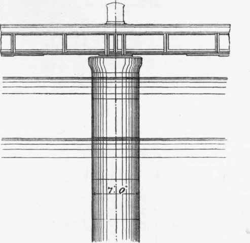
Fig. 358. Scale 1 inch = 12 feet.
Details of the cap to the column are shown in Fig. 364 in section, and in plan in Fig. 365.
The outline of the cap is designed with simple and easy curves, as shown, without projecting mouldings, in order that small floating craft, such as barges, etc., may not catch their coamings or fenders on a rising tide, the cap being but a short distance above high water.
The make-up length, to allow of deviations from regularity in the final level to which the cylinders are sunk, is the one immediately below the cap, as shown in Fig. 358.
The lower portion of the cylinder is shown in Fig. 366. The three lowermost rings are 10 feet in diameter, 1 ½-inch metal, being enlarged to give greater area for bearing, and working space for excavation and sinking operations. The connection between the lower rings of 10 feet diameter and the upper rings of 7 feet is made by the conical length shown in Fig. 366.
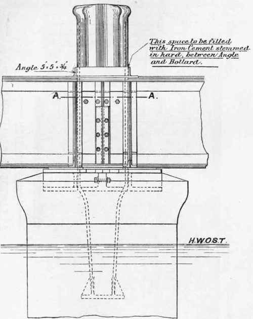
Fig. 359. Scale ⅜ inch = 1 foot.
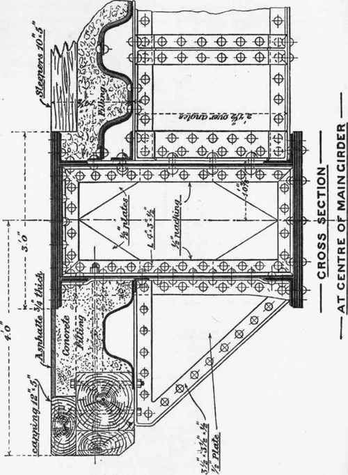
360 (Scale ¾ inch = 1 foot).
Fig. 367 is a section of the 7-feet ring at AA, Fig. 366, and Fig.
368 is a section at BB, looking up, and showing the interior of the conical length.
The cutting edge of the lowermost length of 10-feet cylinders is shown in detail in Fig. 35, the bottom portion, 8 inches in depth, being thickened out to 2 inches, strengthening the cutting edge.
A further use of iron or steel in the construction of marine works in wharf or dock walls may be found in the construction of heavy tie-rods, which are occasionally found necessary to prevent forward movement of walls due either to weakness of foundations, or heavy surcharged loads (the wharf wall being considered as a retaining wall), such as coal stacks, etc.
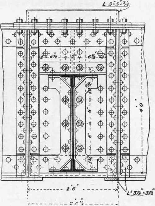
Fig. 361. Scale ¾ inch = 1 foot.
An example of such tie-rods will be found in Figs. 369 to 376 inclusive, which represent the details of a tie-rod for anchoring back the summit of a wharf wall to a rubble mound considerably in the rear of the wall. The rod is 2½ inches diameter in the main section, of mild steel, jointed as shown in Figs. 369 and 370, which show the details of the coupling boxes. The rods are swelled at the ends by means of an hydraulic forging press, and "plus" threaded. The coupling boxes are shaped as shown, while the material of which they are made is described in the results of the tests given on p. 45. The detail of the attachment of the tie-rod to the wall is given in Fig. 371, a recess being cut or left in the face of the wall, into which the cast-iron washer, shown in the figure, is inserted, the whole being flushed up with fine Portland cement concrete, thus preserving the face of the wall intact and preventing obstructions.

Fig. 362. Scale⅜ inch = 1 foot.
The anchorage of the other end of the rod is shown in Fig. 372, where the tie-rod is shown forked into two 2-inch diameter branches, taking hold of a concrete block of such dimensions as to prevent its being dragged through the rubble in which it is embedded.
The junction of the three rods is shown in Figs. 373, 374, and the anchor plates in Figs. 375, 376.
363 (Scale ¾ inch = 1 foot).
The whole of the tie-rod is embedded in a rough pine-wood box, and rammed round with a mixture of sand and pitch to preserve from corrosion, the rod being buried in the filling some feet below the surface.
The use of the concrete anchorage as described above is an exceptional case, the tie-rods being used mainly in the tying together of two parallel wharf walls, the rod passing through from the face of one wall to the face of the other.
Fig. 364 (Scale ⅜ inch = 1 foot).
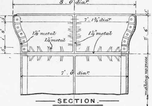
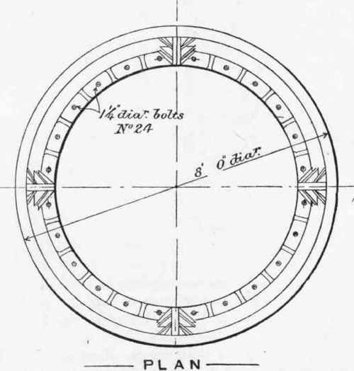
Fig. 365 (Scale⅜ inch = 1 foot).
Continue to:
My Books

