Upon Certain Applications Of Riveted Girderwork, With Some Remarks Upon Rivets And Rivet-Holes. Part 2
Description
This section is from the book "Notes On Construction In Mild Steel", by Henry Fidler. Also available from Amazon: Notes On Construction In Mild Steel.
Upon Certain Applications Of Riveted Girderwork, With Some Remarks Upon Rivets And Rivet-Holes. Part 2
The fundamental rules which, after the proper determination of the mechanical elements of the strength of the joint has been made, will govern the general design are: the grouping of the assemblage of rivets on the centre line or line of action of force of the connected members; the reduction to a minimum of loss of section; the proper pitch of rivets, which for certain classes of joints sometimes requires to be as close as possible to avoid clumsiness;1 the minimum distance from edge of rivet-hole to edge of member to avoid any risk of bursting out; and, lastly, the accessibility of all parts and the provision of sufficient space under all conditions for the operations of riveting and holding up. These rules, if carefully followed and intelligently applied, should lead to satisfactory design. But the study of good examples will be more instructive to the young draughtsman than verbal instructions, however complete, and it is hoped that some assistance will be derived from the examples figured in the following pages, where the riveting is distinctly shown, although the general scale of the construction may be but small.
1 In water-tight work and for boilers or receivers rivet spacing is governed by practical consideration of caulking, and the necessity for a sound water or steam or air-tight joint.
The student who, in the course of his inspection of the methods and practice of a girder-maker's or bridge-building yard, observes the process of work carried on by the punching machines, will find one of the results of that operation to consist of a heap, under the machine, of punchings, or, as they are usually called, "burrs,"1 being the circular discs of metal forced out of the plate or bar in the operation of forming a "punched" rivet-hole. The precise shape and size of the burrs will vary with the diameter of rivet to be employed and the thickness of the material through which the hole is made, but in general will exhibit the features shown in Figs. 16, 17, which are f full-size sections through burrs from punched holes intended for a ¾-inch rivet through a ¾-inch plate or bar, the precise features of the upper and under surfaces of the burr varying with the type of punch employed, the flow of material prior to, or simultaneous with, the final shearing of the circumferential area being shown by the bulging of the under surface of the burr as shown.
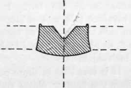
Fig. 16.
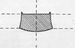
Fig. 17.
If the student now lays, say, three of these burrs together, so that their circumferences are in close contact, as shown in Fig. 18, it at once becomes evident that the burrs are not portions of cylinders, but portions of cones, the angle of the cone being determined by the amount of clearance between the punch and the die, the greater the clearance the greater being the departure from a truly cylindrical form. Thus, as the burr is conical, the hole in the plate or bar is also conical, and we arrive at one of the distinctive features of a punched hole.

Fig. 18.
1 For the use of "burrs" in the formation of special concrete in ballast of maximum density, see p. 402.
Callipered measurements from burrs will show an average difference of about 1/10 inch between the larger and smaller diameters of the burr, being equivalent to a rate of slope in the side of the cone of about 1 in 8, in plates of from f inch to ½ inch thick.
It is true that in those cases where two bars or plates are to be riveted together (and two only), as shown in Fig. 19, and the holes have been punched from the meeting or "faying" surfaces, the double cone produces an approximation to a double countersink, and is not so far objectionable, as it possesses in itself a certain element of strength to resist pulling apart of the plates, even if the heads and points were absent.
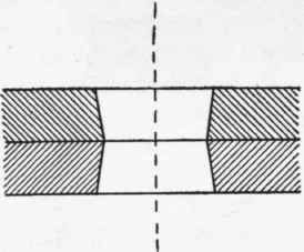
Fig. 19.

Fig. 20.

Fig. 21.
But where the number of thicknesses to be riveted together exceeds two, we have a condition of affairs which may assume a variety of shapes according to circumstances, as sketched in Figs. 20, 21, although by a use of the conical drift, which can hardly be called legitimate, some approximation to a roughly cylindrical hole may be obtained at the cost of a considerable amount of rough usage and distress of the surrounding metal. Thus far we have assumed the axis of the conical holes to be perfectly straight, or, in other words, that the holes have been truly centred one over the other in all the thicknesses passed through. If this be not so, the conditions become aggravated, the quality of the work deteriorates in the same degree, while the illegitimate use of the drift becomes still more pronounced.
The ideal rivet-hole is truly cylindrical, each hole in each thickness of plate or bar being exactly concentric with the adjacent holes, so that the axis of the cylinder remains perfectly straight and square to the plane of junction, whatever be the number of thicknesses joined. These conditions are only perfectly attained when the holes are drilled through all the thicknesses of plates at one operation, and this method is frequently adopted in special cases, or where the conditions or importance of the work render such a course desirable, multiple drills being sometimes employed, by which the position of a number of holes can be simultaneously and very accurately determined with respect to each other. But for the ordinary run of structural steelwork with which we are here mainly concerned, a process such as this is found costly or inconvenient, and other means must be adopted to secure not only that the holes in separate plates shall be truly concentric when assembled together, but also that their pitch or position with respect to each other shall be accurate.
Continue to:
My Books

