Applications Of Riveted Girderwork, With Some Remarks Upon Rivets And Rivet-Holes. Part 3
Description
This section is from the book "Notes On Construction In Mild Steel", by Henry Fidler. Also available from Amazon: Notes On Construction In Mild Steel.
Applications Of Riveted Girderwork, With Some Remarks Upon Rivets And Rivet-Holes. Part 3
In punched work the holes in each individual plate or bar are punched separately, and this is also the case with drilled work, except in the special cases above mentioned. It is, therefore, in the assembling of these separate parts together prior to the insertion of the rivet that the accuracy or want of accuracy of the methods adopted becomes evident, and the examination of the holes for rivets or other connections becomes an important part of the duty of those who may be charged with the inspection of riveted steelwork.
In the bulk of structural steelwork of good quality the method by which the accuracy of the setting out of rivet-holes is maintained is that known as the "templet" system, and the "templet shop" in a bridge-building or girder-building yard occupies an important position, inasmuch as the care with which the work is set out in this shop is a very powerful factor in the ultimate quality of the finished work. The templets employed are sometimes of iron, but generally of wood, and the setting out of templet work may be described as careful full-size draughtsmanship on wood, each rivet-hole being accurately set out in its correct position, whether it be a hole near the edge of a plate, a hole in an angle cover, or in any other position required, and bored through the thickness of the templet, to suit the size of a centre punch, which, being passed through the hole in the templet with a blow from the hammer in the hand of the plater, marks, as shown in Fig. 22, upon the surface of the steel plate or bar the centre of the rivet-hole which is subsequently punched or drilled out.
The next stage of the process is one which at first sight appears to offer opportunity of error which would go far to destroy the original accuracy of the templet, for as the bar or plate (frequently of considerable dimensions and weight) is passed through the punching machine, the operation of placing the centre-punch mark exactly under the centre of the punch demands skill of eye and hand (assisted sometimes by certain mechanical devices, such as racks, etc.) on the part of the mechanic in charge of the machine. A very considerable degree of accuracy may nevertheless be attained, as is proved when good work of this class is assembled together.
Excellent work can be produced by a system which stands intermediate between punched and drilled work and partakes of some of the advantages of both. Each rivet-hole is first punched out, the largest diameter of the punched hole being from 1/16 inch to ⅛ inch less than the diameter of the finished drilled hole. The plate or bar is then transferred from the punching machine to the drilling machine, and the punched hole is enlarged, or rimered, to the finished diameter required, as shown in Fig. 23. It follows that the conical hole has disappeared, together with a certain zone of metal which may have been overstrained or distressed in the process of punching, and is replaced by a truly cylindrical hole. As, however, the point of the drill, or rimer, in entering the punched hole is guided in direction by that hole, the axes of the punched and drilled holes remain the same for all practical purposes, and any material error in position of the punched hole is not modified in the process of drilling.

Fig. 22.

Fig. 23.
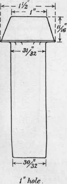
Fig. 24.

Fig. 25.

Fig. 26.
Notwithstanding, as above stated, excellent work is produced by this method, and the accuracy of the holes when assembled together can be made to fulfil all requirements of first-class work, though not equal to that which would result from the process of drilling through all thicknesses at once.
Certain roughnesses left on the surface of the steel plate or bar at the edges of the holes as the tool enters or emerges from the hole should be scraped off before the meeting surfaces are placed together for riveting, as they tend to prevent close contact.

Fig. 27.
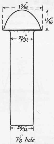
Fig. 28.

Fig. 29.
Details of the mechanical tests of mild steel for rivets are given in Table No. 14, p. 41, and the chemical analysis of a sample for the same purpose will be found on p. 52.
A comparison of the rivets manufactured by various makers and commonly used in constructional steelwork will show certain variations in the shape and dimensions of the heads.
Figs. 24 to 32 have been drawn and measured from actual specimens as manufactured and used by well-known firms in this country. As a rule, mild steel rivets have heads and points somewhat heavier than those employed for wrought-iron rivets.
Figs. 24, 25, 26, show pan-headed rivets, and Figs. 27, 28, 29, show one type of cup-headed rivets, while Figs. 30, 31, 32, show cup-headed rivets of somewhat different shape. For the combination of punched and rimered holes above described there will be a difference of about 1/32 inch between the diameters of the hole and the rivet to allow for entry. The student will consequently appreciate the distinction between a rivet figured for, say, 1 inch hole, and a rivet figured as 1 inch diameter, and as by the terms of most specifications the rivet is to fill the hole, a rivet, say, of 31/32- diameter may for purposes of calculation be reckoned as 1 inch diameter when completed.
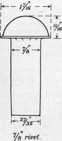
Fig. 30.
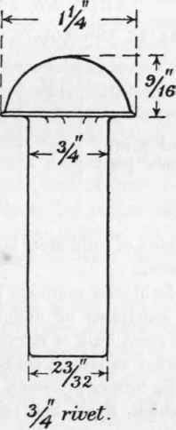
Fig. 31.
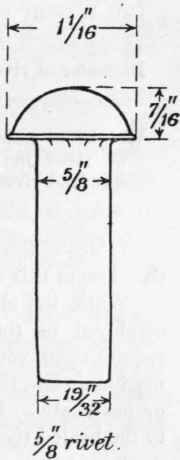
Fig. 32.
In the estimation of weights of structural steelwork the weights of the heads and points of rivets (except where countersunk) must be allowed for. The actual percentage will vary slightly in different classes of work, being greatest in those cases where the riveting is heavy relatively to the thicknesses of plates connected and the pitch close. About 4½ per cent, will, as a rule, be found sufficient for heavy girderwork, but a more reliable estimate in individual cases is arrived at by counting the rivets where practicable and allowing the values given in the following table, in which the point or snap of the rivet is assumed to be of the same weight as the type of cup-head shown in Figs. 27, 28, 29.
Table No. 30. The Weight Of Heads And Points Of Mild Steel Rivets
Diameter of rivet ... | ½" | ⅝" | ¾" | ⅞" | 1" |
Weight of head and point of rivet in pounds per hundred rivets | 9 | 13 | 24 | 35 | 50 |
Tables of the weights of mild steel bolts and nuts are given at the close of this chapter.
While the older-fashioned methods of hand-riveting are still employed in those situations or under those conditions which require them, yet the great bulk of riveting is now carried out by machine-work, the power employed being usually either hydraulic or pneumatic. In the former process a steady pressure is applied to the heated rivet, which, if allowed to remain on long enough, produces a thorough filling up of the hole in a manner winch cannot be surpassed. In the pneumatic or compressed air method the process may either be one of steady pressure, or of a succession of rapid blows produced by the tool known as the pneumatic hand, hammer, which, albeit somewhat noisy, has proved its efficiency in this direction, while similar processes are applied to caulking, drilling, and other mechanical work. A pneumatic holder-up is also used in connection with the hand-hammer, but is often replaced by the older hand method where convenience requires.
Some difference of opinion exists as to which of the methods, hydraulic or pneumatic, as applied to hand-hammers, produces the soundest work in closing up the rivet. There is no doubt that good work can be produced by either mode, and the formation of the snap-head by the hand-hammer can be completed with great neatness and finish.
The pneumatic hand-hammer also finds a place in certain processes as much associated with architecture as engineering, being used in the dressing and carving of stonework.
Continue to:
My Books

