Equal Tapering Rectangular Article
Description
This section is from the book "Practical Sheet And Plate Metal Work", by Evan A. Atkins. Also available from Amazon: Practical Sheet And Plate Metal Work.
Equal Tapering Rectangular Article
The plan of a rectangular hopper or hood is shown in Fig. 51, t®gether with the necessary construction lines required for the patterns and the corner angles.
In setting out the plates the first thing required is the length down the slope of the hopper, and this can be found by marking off a b equal to the depth of the hopper, and drawing the line a c square to it; then c b will be the required length down the slope, This length will, of course, give the width of the plate, which, to avoid setting out, might be calculated thus: -
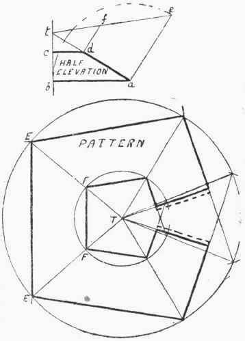
Fig. 60.
Width of plate = ![]()
To illustrate the above by an example: Suppose the top of the hopper is 15 ft. by 11 ft., the bottom 7 ft. by 3 ft., and the depth 9 ft., then the overhang will be -
15-7 /2 = 8/2 = 4ft .
The width of the plate will equal -
![]()
9 ft. 10 1/8 in.
Having set down the centre line, B C, to this length, for the side-plate, the lines H D and A M are drawn square to it, and marked off equal in length respectively to h d and a m. In the same way, the end-plate can be marked out, H L being equal to h l, and A N to a n. If flanges are to be turned on the side-plates, then laps must be left on, as shown. The notches on the laps can be formed by fixing the leg of the compasses at any points on D M and D M produced, and drawing arcs of circles to touch H D and A M; then drawing lines to touch these arcs, as at P M and the other corners. Without it is an exceedingly particular job, notches are not left on the bottom corners of the plates, on account of the difficulty of working and waste of material, but are sheared straight along, as shown by the line A K.

Fig. 51.
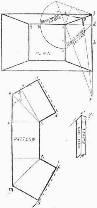
Fig. 52.
If the plates are not to be connected by flanges, but with corner angles, then it will be necessary to make a template, showing the rake of the angle-iron. The construction for this is shown on the plan in Fig. 51. Draw f g square to d a, cutting off a b' equal to a b. Join b' to d, and draw a e square to b' d. Make a e' equal to a e, then the angle g e' f will be the required rake that the corner angle-iron must be set to.
Another construction for the same kind of thing is shown in connection with Fig. 55.
Continue to:
My Books

