Tanks
Description
This section is from the book "Practical Sheet And Plate Metal Work", by Evan A. Atkins. Also available from Amazon: Practical Sheet And Plate Metal Work.
Tanks
A most interesting example of a particularly simple method of jointing is that used in the construction of tanks, when the plates are flanged and lapped and no angle-iron used. Fig. 293 shows the outside view of such a tank. It will be noticed that each face of the tank has two lines of rivets upon it: hence it can be seen that the tank will be constructed of six plates, each plate having two flanges. Fig. 294 is a view of an inside corner which should readily explain the arrangement of the laps on the three plates. An outside view of the same corner is shown in Fig. 295. It will be observed from both of these views that the laps are so formed as to leave a hole right in the corner of the tank. After the tank is riveted up along the laps, the holes at corners are either drifted or reamered out, and a special corner rivet put in as shown on Fig. 293.
The setting out of a plate is explained by the aid of Fig. 296. A cubical-shaped tank has been chosen for the sake of simplicity. The length, breadth, and depth of the inside being the same, by inspection of the arrangements of the plates and joints, it will be seen that each plate is exactly the same: hence if a template be made of one plate, the other five can be marked from it.
A section of one plate covering two joints is first set out as shown (the thickness of plate is enlarged somewhat to better show the construction lines), and from this both the length and width of plate can readily be obtained. The length of plate will be found by measuring the distance along the centre line of section, and the width will be equal to the length of flat part of plate - in this case A B. The length and breadth of plate can, of course, be calculated as in the cylindrical shell. Thus, suppose the inside dimension of tank to be 4 ft., and inside radius of plate to which the flange is bent ¼ in., thickness of plate 1/8 in., and lap 1 1/8 in.
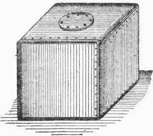
Fig. 293.
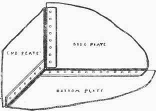
Fig 294.
Rule for width of plate: -
"Deduct twice the thickness of plate and twice the inside radius of flange from the inside dimension of tank."
Width = 48 - 2 (¼ + 1/8) = 48 - ¾ = 47 ¼ in.
Rule for length of plate: -
"To the width of plate add 3 1/7 times the radius of centre line and twice the lap."
Length = 47¼ + 5/16 X 3 1/7 + 1 1/8 X 2 = 50 27/56 = 50½ in. (nearly).
There should be no difficulty in marking out the holes on plates, as each line of holes is exactly the same. A good method to pursue is to make a template of hoop iron or a batten of timber, with a line of holes carefully set along at the required pitch. From this, all the holes can be marked, and it will avoid the lifting about of a heavy template, which would happen if one of the plates were used for this purpose.
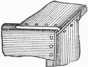
Fig. 295.
All rivet-holes can of course be punched before the plates are flanged. The gauge for marking the width of flange from edge of plate will be the distance measured along the centre line of section from the end of plate to middle of bend. It can also be calculated by the following rule: "To the lap add one-quarter of 3 1/7 times the radius of centre line of section."
Width of flange -
= 1 1/8 + 5/16 X 3 1/7 X ¼ = 1 83/244 = 1 3/8 in. (nearly).
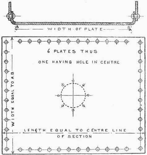
Fig. 296.
The cover is bolted on with set screws, and the holes for these are drilled and tapped to suit the screws.
Whilst a cubical tank has been described, the above remarks and calculations can of course be easily modified and applied to suit the case of any sized tank with either open or closed top.
Continue to:
My Books

