


A Model Electric Railway. I. The Track
Description
This section is from the book "Amateur Work Magazine Vol1". Also available from Amazon: Amateur Work.
A Model Electric Railway. I. The Track
A model electric railway probably affords more pleasure and instructive occupation for leisure time than anything which an amateur can make. Many of the readers of this magazine will undoubtedly be interested to learn how to make one which will work well and yet be inexpensive and simple in construction. The one here described is of this description, yet any one so desiring can elaborate these designs to quite an extent by putting in more detail than is here given. The system is that known as the "Third Rail," so named from a third rail which conveys the current to the motor, the track forming the return circuit. The parts to be described will include the track, switches, cross-track, bridges, turn-table, etc., also motor car and other rolling stock, and other fixtures of a regular railway. The aim in the preparation of these designs has been to keep the cost of making them at the lowest point consistent with serviceable results.
The materials for the track include several pieces of Venetian iron 3/16" wide. This is sold by hardware dealers in coils of 50' at fifteen cents. It is easily worked with drill and file, and with proper care no difficulty will be met in shaping it.
It is fastened with small wire nails to strips of whitewood, maple, spruce or other suitable wood 3/16" wide and 1/4" thick. When the length of track has been determined, the necessary number of wooden strips can be ordered from any woodworking shop for a small sum. The pieces for the third rail are 3/8" thick, and the strips for the sleepers should be 1/2" wide and 1/4" thick, with a few pieces 1" wide for switches and cross-track. A hand-drill will be needed for drilling holes in the iron for the nails, which should be about 4" apart. Fluted drills are better than diamondpointed ones for this work; twist drills are too easily broken. Punching the holes is not desirable, as it bends the iron so much that it is difficult to get it straight again. Countersink each hole slightly with a drill of the size of the nail head.
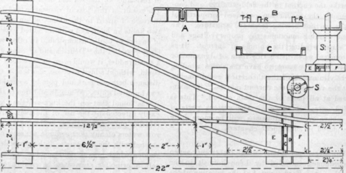
To make a section of track, cut two pieces of iron, allowing 3/4" extra length for the fastenings at the ends, and two pieces of wood for the rails, and a suitable number of pieces for the sleepers, which are spaced not over 6" apart, and as much closer as one may desire. Drill and countersink the holes for all the nails, bend 3/8" of one end at a right angle, as shown at A, Fig. 1. Place tho same on one of the strips of wood and carefully nail with 3/8" wire nails, of the kind used in making cigar boxes, clinching the end on the under side. This prevents the nail from working loose. Do the same with the next hole, and then with a light hammer tap the rail until it is perfectly level. Continue until the whole rail is nailed and leveled, the other end being bent down for the joint, as previously mentioned. Then file down the heads of the nails until level with the track. But little filing should be required if the nails are the right size and the holes have been counter-sunk, and the rail should present a firm, level surface, well suited for even running of the cars. When both rails have been thus prepared, place them parallel and 2" apart, with the iron on the under side ; a 2" gauge will probably suit most requirements, that is, 2" between tracks. This allows the use of equipment made in Germany, and also by Carlisle & Finch, Cincinnati, Ohio, which is for sale in most of the larger cities throughout the country, and may be purchased by those desiring to do so.
The sleepers are 1/2" wide, 1/4" thick and 4" long One running rail is placed 1/2" from one end of the sleeper, and the sleeper then carefully nailed to the wooden strip of the rail. The sleeper is then nailed to the other rail, the sleepers at the ends of each section being about 1/2" from the ends, as the wooden strips of the rails are liable to split if the sleepers are at the ends. A cross-section of the track is shown at B, Fig. 1; RR are the running rails, and T the third rail. The third rail is made in the same way that the others are, with the exception that ribbon brass fa" wide is used in place of the iron. This costs about thirty-five cents per pound, and one pound will do for about 50' of track. Brass nails should be used for fastening to the wood, which should be about 1/8" higher than the track, so that the collector shoe on the motor car will not touch the track at switches and crossings and short-circuit the current. Sections of the third rail are joined with U-shaped pieces of brass, the ends of the third rail being bent over the same as with the iron rails. The third rail is placed 1/2" from the inside running rail.
In making curves and switches, the best results will be secured if a full-size pencil drawing is first made on manilla paper. To curve the iron or brass, hold it edgewise on two pieces of hard wood about 1" apart, and hammer the upper edge until the proper curve is secured. After bending, it will probably be necessary to level it with a hammer, as previously directed. The wood for curves should be slightly green, as it bends better if in that condition, while well-seasoned wood will be more easily broken. The best way is to nail the curved iron or brass to a piece of wood of the proper thickness, and wide enough to permit surplus wood to be cut away with a fret-saw or draw-knife, leaving only that needed for the rail. In this case the wood pieces are 8" to 12" long, and it will be found much easier to make curves this way than trying to bend long strips; but care must be used in driving the nails to avoid splitting the wood. The nails should be about 3" apart on curves. If the curve is a sharp one, the rails may be fastened to a piece of thin board, instead of to sleepers.
The way to make a switch is clearly shown in Fig. 1. It will be noted that the outside rails are continuous, the inner ones being broken. The points are connected by a piece of the rail iron C, which is bent as shown at C, Fig. 1, the projection on each end fitting into a recess cut in the wood, and has a hole drilled through it. The nail which fastens down the iron rail goes through this hole. A hole is drilled through the center to receive a round-head screw, which fastens it to a piece of wood, D, which slides between the two sleepers, E and F. The other ends of the points are held by screws which are put through from the under side into the wood of the rails, holes being drilled in the sleeper to allow the screws to turn easily. A spool 1" in diameter is nailed to the sleeper, as shown at S, a small square section first being cut out of both sleeper F and the switch-piece D, as indicated by the dotted lines. A wooden skewer is then cut to suitable length, and in the lower end, and also at the point where it projects above the spool, holes are bored to receive L-shaped pieces of steel wire. The lower one, moving in the slot in the switch-pieces, D, causes the latter to move whenever the upper one, representing the lever, is moved. To the upper end of the skewer is attached a small piece of wood, painted to represent a switchboard, and so placed that when the switch is open it will be at right angles with the main track, or a block may be used to represent a switch light, green showing when the switch is closed, and red when it is open.
The outer ends of all rails are bent down as previously described, to form the joints with other sections. The ends of the third rail at switches and cross-tracks are depressed slightly, so that the shoe will pass over them without catching. Sections of the third rail at such places are connected by lengths of insulated wire, which should be soldered to the third rail. A blow-pipe will be the best for such connections, the rail and wire being first carefully cleaned with a file. Any inquiries that readers may find necessary will be answered through the correspondence department of this magazine.
Continue to:


My Books

