


A Model Electric Railway III. The Track
Description
This section is from the book "Amateur Work Magazine Vol3". Also available from Amazon: Amateur Work.
A Model Electric Railway III. The Track
Robert Gibson Griswold.
For the successful operation of a model railroad, it is essential that the track should be especially well designed and built. A model seldom has the proportionate weight to keep it to the rails, and any slight inequality in the rail may tend to lift the wheel off the tread. Much, of course, depends on the finish of the wheel flange and tread.
In the construction of frogs and switches, care must be taken to have the points and joints well smoothed off, and the relative parts securely fastened together. As far as possible, in keeping with simple amateur construction, the track equipment will follow closely the designs in use on the standard railroads.
In Fig. 1 is shown a section of double track including two split switches and two single frogs. Since this is designed as a "third rail" system, it is necessary that the third rail should be mounted on either side of the track just outside the rail. This system, while requiring about double the quantity of third rail, is far better than the single rail especially where switches and frogs occur. If the car is moving slowly over these places the current may be entirely shut off the motor and it will come to a standstill.
Another method is to provide the car with two sliding shoes, one on either side which will materially reduce the resistance of the system. When two shoes are provided, the double third rail may be omitted except at switches and frogs.
When the car passes these points one of the shoes will be in contact with a rail at all times and no break in the current will ensue. This is perhaps the most satisfactory arrangement. It will then make no difference in what direction the car travels, as a shoe is carried on either side of the car.
At a, Fig. 1, is shown the end elevation of the rails and a tie. The gauge of the rails is 2 1/2" and the third rails are set 1/2" outside the rail-head. The rail used in this system is a special form made of rolled strip brass which may be obtained in six-foot lengths, is straight and true to size and the head is nicely formed. It can be fastened to the ties by small gimp tacks which have a button head, setting nicely over the flange of the rail. The third rail is merely a strip of brass bent into the shape of an L and secured to the ties in the same manner. If preferred, strips of metal may be substituted for the wooden ties and the rails soldered thereto. The ties are four inches long, by one half an inch wide, and one quarter of an inch thick.
The rails above mentioned can readily be joined together by means of a stud driven into the head of one of the abutting sections, the rail-head being hollow. File up such a stud from brass wire and fasten one into each rail with a little solder, leaving the other end hollow. Sections thus provided will match exactly and form good electrical contact. The third rails may be joined by soldering to each side of one end, a small strip of brass thus forming a slat into which the abutting rail may fit and secure good electrical contact.
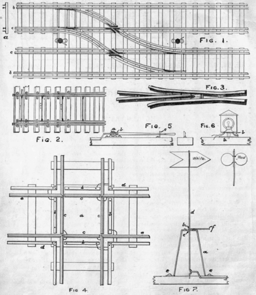
In making curved sections the rails should be annealed by heating to a dull red and plunging into water, (the railing having rendered the brass very hard) lay out the curve desired on a 1/2" board and carefully bend the rail to fit. Do not allow the flanges to double up while bending, as they have a tendency to do, but keep them fiat by hammering, as the bending proceeds. The inside rail, of course, has a lesser radius than the outside, and the board may be cut to its arc after the outer rail is finished. Make the approach to each curve very gradual so that the cars will take it easily.
In Fig. 2 is shown a knife switch drawn to a slightly larger scale than Fig. 1, showing the detaits more clearly. The rails are not cut for this form of switch as in the stub switch. The outside rail b, is curved straight while the inside rail is curved to form the end of the switch, and terminates in a point at the frog in the inside rail of the adjoining track. Take a piece of rail and file the end down to a long thin point and raise the flange so that it will clear the flange of the rail against which it lays. There should be no abrupt change at this point but the tapered end should lead away from the rail very gradually for at least a distance equal to the gouge. Make two such pieces for each switch and bend one to the curve of the turnout as shown in Fig.
1. These tapered rails are connected together by tie-rods shown numbered in the figure as Nos. 1,
2, 3, and 4. These tie rods may be pieces of wire soldered to the rail flange and are provided to keep the rails the correct distance apart and move them simultaneously. The rails are fastened to the ties directly beyond the last tie-rod and the further away from the point that the first fastening occurs, the more flexible will the switch be. One of the tie-rods, generally No. 1, is extended to one side for attachment to a ground lever for throwing the switch. In this case the wire may be bent down slightly to allow it to pass beneath the rail.
The frog will present the greatest difficulty in construction. The joints must be made smooth and nicely tapered. Fig. 2 is an illustration of a standard frog which shows the details of construction very clearly. Instead of placing a block between the tracks as here shown, solder the various pieces to a brass plate which will make a very solid and substantial frog. Lay the frog down on paper first so as to more readily measure the tapers required and then cut the rail to fit as designed. In all frogs the gap is so proportioned that when the wheel is passing over it the tread will rest on the rail beyond before it leaves the point, thus relieving this point of the great weight which would soon smash it. Do not allow more space for the flange between the tracks than necessary. In the practical use of frogs on railroads, a guard rail is provided, lying close to the outer rail but on the inside, allowing just sufficient space between the two heads for the flange to pass. The purpose of this extra rail is to prevent the wheel slipping to one side further than it should, and climbing upon the point of the frog which would, of course derail the train.
The third rail should be about 1/32" higher than the track-rail, so that the shoe will not cause a short circuit as it passes over the breaks. If care is taken in fitting these third rail sections, very small gaps can be secured and the sliding-shoe will pass over them freely in either direction. Wherever a break in this rail occurs, as at points where it crosses the track-rail and comes close to the frog, taper the ends towards the flange so that the shoe may not catch. Connect the various sections of third rail together by soldering wires thereto, so that no section will be " dead " when the car passes over it. It is also a good plan to connect the track rails together by soldering a wire between, at least one in each section. This will be found to materially reduce the resistance of the circuit, especially if one of the rail connections should be faulty.
In Fig. 4 is shown a cross-over together with the third rail and connections. The middle block a, is best made of one piece, and in the event of the crossover being made in a separate section, the piece a had better be extended to the position occupied by the ties shown. This method of construction will give support to the rails and prevent distortion should the section be lifted by one end, the design shown being intended for a permanent position. The sections of third rail b must be connected by wires to the live rails d as shown, which will enable the car to pass this section.
Mitre the joints of the rails and solder together to form a solid piece. The short rails c, must also be connected with the main rails e, so that the electrical continuity of the tracks may be preserved.
In Fig. 5 is shown a ground lever for throwing a switch. This lever is pivoted at a to a stand which is fastened to the tie. At b a link is pivoted which is fastened to the tapered end of the switch. In throwing the switch the lever is thrown over and hooked under the catch c, which holds it in place against the tension of the switch. A switch stand is shown in Fig. 6 which turns with the switch and shows a red or white light, depending on the switch position. Make a little stand a, of brass so that a stud fastened to the bottom of the lamp can pass through a hole and turn therein. To the bottom of the lamp is attached a short lever b, to which is fastened a link attached to the switch. This causes the lamp to turn a quarter turn with a full throw of the switch, showing white when closed and red when open. Make the lantern body of wire and provide the openings in the side with red and white glass. Inside the body is mounted a small pea lamp, connection with which is made by two wires passing through the bottom. Adjust the lamp so that it will show white when looking along the main track, while the switch is closed and red when the switch is open.
A vertical switch lever and target is shown in Fig. 7. The stand a, is bend up from a 1/4" strip of No. 20 hard brass to the shape shown. Drill a hole at c, for the rod d to pass through and two in the ends for screws e. At the upper end of the target rod is fastened a target made of tin and painted in the colors indicated. The connection with the track is so made that the target will show white when the switch is closed and red when open. A handle f"is soldered to the target rod at b with which the rod is turned, thus throwing the switch.
Continue to:


My Books

