Elements Of Dynamo Design. Magnetic Circuits-Field Magnets. Continued
Description
This section is from the book "Amateur Work Magazine Vol6". Also available from Amazon: Amateur Work.
Elements Of Dynamo Design. Magnetic Circuits-Field Magnets. Continued
Another magnetic property of iron and steel is Hysteresis. This is a lag in the building up to their full number of the lines of force in the iron behind the force which producees them. In other words, there is an appreciable time between thee application of the force and the building up of the lines to the full number. Hysteresis is much less in soft iron than in steel. Reversals of magnetism take place every revolution of the dynamo, so it is necessary to make the core of as soft a grade of iron as possible. Hysteresis is a loss, and shows itself as heat in the iron, which accounts for some of the heat in the armature core. This, however, is a more important factor in alternating current design, especially transformers, as there large masses of iron are subjected to the reversals.

Fig. 7.
Having mastered some of the fundamental principles of magnetism, the field magnet will be the first part of the dynamo to consider although in the actual design of the machine it is the second part to calculate, the armature being the first.
The magneto-motive-force required to drive a given number of lines through an iron core, or across an air gap, depends upon the reluctance of the iron and the number of lines of force. Let H equal the magneto-motive-force, N the total flux, and R the reluctance, then,H = NR. (4) But from formula (1) H -kIS. then k I S = NR (5) When the unit of length and area is given in inches k equals 1 H- 0.3132 therefore the ampere turns
I 8 = NR 0.3132 (6)
It was previously determined that the reluctance of a magnetic circuit varied directly in proportion to its length and varied inversely to its area and the permeability of the iron, that is,R = 1/A and formula (6) will be,I S - N 10.3132 A It will be readily seen from Fig. 6 that the length of the magnetic circuit is divided into at least three parts having different magnetic characteristics. This figure of a simple dynamo in which l1 represents the average length of the armature magnetic circuit, l2 the aid gap and P the average length of the lines of force
This formula can be presented in another form which may be a little easier to handle. Since N A equals the unit density B, then (8) would become I S equals B 1 0.3132 and assume S = 1 in., then for each inch of length of the magnetic circuit the ampere turns required will be B 0.3132
IS = 10)
From this formula can be had two variables, ampere-turns (I. S.) and lines per sq. in., B, and by using these as ordinates and abscissae, a curve can be plotted giving at a glance the ampere turns required for every inch of magnetic circuit, air or iron, with a through the held. Then the ampere turns for the armature would be N 11 4- A 0.3132 where is the permeability and A the sectional area of the field core. As the permeability of air is 1, the ampere turns for the two air gaps would equal 2 N 1 4- A Due to the fact that there is a certain amount of leakage of lines of force around the field poles, which do not enter the armature, the flux will have to be increased by an amount v which varies according to the types of field frame, and the capacity of the dynamo, from 1.1 to 1.4. The ampere turns for the field will therefore equal v N 1/3 / A 0.3132. The total ampere turns will then equal

N 1,0.3132 2 N 1/2 0.3132 Nl3 0.3132
I S _ I ----------------- + -----------------------IS i 1 At A2 A3
1 212 l3v or I S = N 0.3132 1/A1 + 2l2/A2+l3/A3 which is the formula to use when length and area is given in inches.
given magnetic density. Such a curve is given in plate I. Curve A is laid off with ampere turns per .01 inch of' air gap for ordinates, and lines per sq. in. for abscissae. Curves B, C, and D are for iron, cast steel and armature punchings respectively, and are laid off with ampere turns per inch of magnetic path as abscissae and lines per square inch as ordinates. These curves should be used with some allowances to make up for variations in the grade of the iron or steel. It is not desirable to work too fine with the numbers, as the results given by these curves are only approximate. Use round numbers. For example, if the curve gave 2523. lines call it 2600; or if 122 1/2 ampere turns are the result of computation make it 125. Liberality of design in this part of the machine will be of great benefit and will help make up dif-ficiencies in other parts.
The form of the field magnet does not matter if it is magnetically and mechanically correct. All parts carrying lines of force should be so designed that they will not offer too much resistance to the magnetism (reluctance), but at the same time should not be so large as to add unnecessary weight to the dynamo and look clumsy. Care should also be used to cut down as much as possible the leakage of lines of force around the armature. These lines would be useless and at the same time would require an extra number of ampere turns above those needed to send the lines through the armature.
An example of bad design in this respect would be to carry the field pole tips well around the armature until they nearly touched. This would allow probably nearly 40 per cent, of the total lines in the field slight leakage from pole tip to pole tip in the air. This is taken care of in formula 9 by the letter V as explained before.
The application of these formulae will be treated in later chapters. The size of wire depends upon the amount of current flowing. The determination of these will also be taken up later, and a table will be given showing the current capacity, diameter of bare wire and with insulation for the different sizes of wire.
There are a number of rules given for determining the direction of the flow of magnetism induced by an electric current. Ampere's Rule, which follows, shows the direction of the field of force which sur-

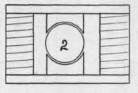

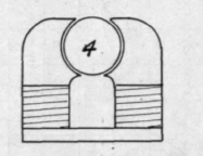
Fig. 8.
to jump across in the air, instead of going through the armature, which is usually crowded to nearly its saturation point. In such a design, therefore, it would be necessary to add 40 per cent, more ampere turns than were actually needed by the armature. In all cases, however, there is a certain amount of leakage of the lines, which either jump from pole to pole in the air, or get back to the other end of the field spool through the air outside the coil. Fig. 7 gives the outline of a dynamo with the leakage shown in dark lines. This is the old familiar Edison type dynamo. It is mounted on a wooden base, which in turn rests on an iron bed plate with sliding rails. The figure shows plainly how many lines are lost in the air, and also that many pass from pole to pole through the bed plate. This type of field is very wasteful of magnetism.
The modern multipolar dynamo is designed to obviate as much as possible this leakage. This type is shown in No. 1, Fig 8. The field poles point inward towards the armature from a solid iron ring which forms part of the magnetic path, the completion of the path being through the armature when it is needed. It will be seen that the iron forms nearly the shortest path for the lines of force. There is, however, a rounds a current flowing in a conductor. "Suppose a man swimming in the wire with the current, and that he turns (his body) so as to face a (compass) needle, then the N seeking pole of the needle will be deflected towards his left hand." In other words, in facing the direction a current is flowing in a conductor, the lines of force pass around the conductor clock wire, or in the direction the hands of a clock move. If this conductor be multiplied into a number of conductors so as to make a coil, and the current in passing along the wire comes up in front and over the top of the coil away from the observer, it is very evident that all the lines from each conductor added together will make a north pole at the left and a south pole at the right. Also, if the current passes down and under the coil away from the observer the north pole will be at the right and the south pole at the left.
Another good rule is this:-Facing a North pole, the magnetizing current would be flowing about it in a counter-clock-wise direction, and facing a South pole the magnetizing current would be flowing in a clock wise direction . If the direction of current is known (which is generally the case), this rule can be used, for if the observer is facing the end of an electro-magnet and finds the current flowing clock-wise, then the nearest end of the magnet is the South pole. Similarly, if the current is flowing counter-clock-wise the nearest pole is North. With these rules, it makes no difference in which direction the current passes along the spiral; that is, it matters not whether the coil is wound right or left handed. These rules are very important and should be memorized.
The forms of field frames are many, and it matters but little what form is used provided it is designed for a minimum leakage, and that the coils have sufficient copper wire to produce the required field of force for the armature. Fig. 8 gives a few standard forms; No. 1 is the multipolar form, which is used almost exclusively at the present time for medium and large size generators. The familiar Edison bipolar is shown in Figs. 6 and 7. Refering to Fig. 8 again, form No. 2 is the Manchester type; No. 3 is an early form of Siemen's dynamo; No. 4 is a favorite type of the present day with some manufacturers for small size machines. It is practically the Edison bipolar in verted, which removes the objectional leakage of magnetism in the base frame. In deciding upon a field frame it is obvious that one with the least number of joints in the magnetic path will require less field excitation and therefore give a dynamo of greater efficiency.
The subject of the field magnet and frame is not by any means exhausted in the foregoing but has only been touched upon. Much has been written on the subject, more in fact than the average student can read. In a later chapter a list of books will be given which the student may examine and study those portion referring to the work at hand.
Continue to:
My Books

