


Small Cabinet Workbench. Continued
Description
This section is from the book "Things To Make In Your Home Workshop", by Arthur Wakeling. Also available from Amazon: Things to Make in Your Home Workshop.
Small Cabinet Workbench. Continued
In the method of procedure, too, the expert and the amateur do not follow the same steps. One good method to use in making the bench from this point is as follows:
Check up on the legs for squareness. If two adjacent sides can be found that are straight and reasonably square to each other, it is not necessary to do any planing, except possibly to clean the surfaces. If they are not square, it is better to plane them down in order to avoid future trouble.
Mark the two face sides of each leg thus selected and plane the other sides until all are the same size, working from the face corner.
Cut the legs to 31 ¼ in. in length, if the height of 33 in. has been accepted. A rather short person may like 32 in. better, and in that case the legs will be 30 ¼ in. The job then will be carried out exactly as shown in the drawing above, except that the distance below the lower rail will be 8¼ in.
It will probably be found that the legs are very nearly 2¾ in. square. If not, it is easier to make allowances in the plans than to reduce the legs to the exact size indicated.
True up the 2 by 3 in. rails on one side and both edges, if necessary, and mark the true face and one edge. Next, if a plow plane is available, run grooves the thickness of the ceiling, as shown in Fig. 13, on one edge of all of them except the lower front rail. Place the groove as in detail No. 1 of Fig. 12. If no plow plane is at hand, strips can be nailed on to receive the ceiling after the joints have been made. Cut the rails to such a length that 1¾ in. is allowed for a tenon on each end. Similarly prepare the three light rails for the front.

Fig. 12. - Leg and rail joints and a horizontal cross section through one end of the bench that is shown in Figs. 10 and 11 ; how the top is fastened and details of the drawers.
Lay out the mortises on the legs. Take care to calculate the reduction required on account of the depth of the grooves as shown in Fig. 14. The upper mortise must not come closer than ½ in. from the top of the leg. Use ½-in. mortises, placed as illustrated in detail No. 2 of the above drawing, Fig. 12.
Bore out the mortises with a ½-in-auger bit, making holes as close together as possible and the entire length of the mortise. Then clean out the hole along the sides with a wide chisel, and at the ends with one ½ in. wide. In boring, care must be taken not to cut through the leg. A bit gage is a convenient tool to use for regulating depth. One can be made by boring a hole through a piece of wood of the right length and sliding it onto the bit. Lay out and cut open mortises in each leg to receive the drawer rails and runs as in detail No. 3 of Fig. 12.

Fig. 13. - Using a combination plane to plow grooves in the rails. Strips can be nailed on instead of making grooves.
Lay out the tenons to fit the mortises, using knife, square, and marking gage. Then cut exactly to the lines with a rip saw for end grain cutting and a crosscut saw for side grain cutting. Some workers prefer to cut a distance from the line with the saw and then chisel to the line.
Now assemble the ends and back without using glue, and nail in pieces ½ by ½ in., or quarter-round molding, on the legs as shown in Fig. 15, to receive the ceiling. These strips can be left off until the entire job is assembled.
Cut the pieces of ceiling to length, allowing not less than 1/8 in. for clearance. Also trim the last piece to correct width so that no delay will occur in the final gluing.
The upper rail on the front is fitted with a dovetail joint as shown in Fig. 16. This is easy to make and adds strength to the bench.
Cut tenons on the ends of the drawer rails to fit the mortises in the legs as shown in detail No. 3 of Fig. 12.
Assemble the ends first, using glue on the tenons but not on the paneling. A good grade of liquid glue is satisfactory. Pull the joints together with bar clamps, if available, and be sure to test the frame for squareness.
It is better to let the ends dry before assembling the whole frame, but if the joints are tight, or if clamps can be kept on the ends, there is no need to wait. Put the two back rails in place, insert the paneling as before; then put the front rails in and set the second end in place. Again, if clamps can be used, the joints can be drawn up tighter. Put the top rail on in front after the frame has been put together.
Now make the top as shown in Fig. 11. The end pieces are glued and screwed on with 3½-m. screws. The bottom of the tool trough is fitted into the frame and fastened with screws (or nails) on one edge and the ends, and a piece of quarter-round molding is laid around it to close the joint. A more substantial job would result from making the top piece from narrow strips and running long bolts through from edge to edge, but the treatment shown here is much easier and makes a strong bench top. Attach the vise before the top is fastened.
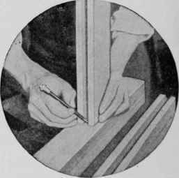
Fig. 14. - Mark the legs by placing the end of each rail in position.
Fit and nail the 2½-in. drawer runs in place against the end and back ceiling; nail through the ceiling as indicated in detail No. 3 of Fig. 12. Fasten the 1-in. guides between the legs and nail through them into the runs.
Attach the top by driving 2¼ in. No. 12 screws as in detail No. 4 of Fig. 12. In front, run screws up through the upper rail. There should be no tendency for this top to pull loose, so all that needs to be done is to hold it in place.
Fit the bench stop. In doing this, first bore a hole for the main part, insert the bench stop, scribe around it, and chisel to the lines.
The drawers are easy to make, for now you have a bench to work on. Indeed, the making of the drawers can be postponed, if necessary, for more urgent work, but it is strongly advised to make them at once in order to have a storage place for tools and materials. They will also serve as supports for wide material that is held for planing as in Fig. 10.
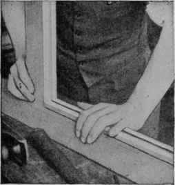
Fig. 15. - Strips are nailed to the legs to correspond to the grooves in the rails.
In making drawers, the grooving for the bottoms, as in detail No. 5 of Fig. 12, is the only problem. If no plane is at hand, it is quite possible to nail on strips all around, as at A1 to make a seat for the bottom, and thus eliminate the groove. Or, if there is a commercial woodworking establishment in the neighborhood, you can get the work done there.
The joints at the front corners are usually the half butt or rabbeted type as at B, while those at the back can be plain butt joints as at C. The back pieces usually are not grooved, but are cut off in width so that the bottom slides under as at D. The bottom is then nailed to the edge of the back. Since plywood does not shrink, many workers now make grooves all around and simply insert the bottom before the drawer is nailed up.
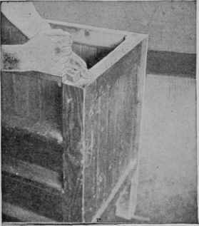
Fig. 16. - The upper front rail is dovetailed into the legs to prevent them from spreading.
Fasten the bench to the floor with angle braces and put in some hooks on the ends to take care of the bench hook, cutting boards, dusting brush, and other articles that cannot be placed conveniently in the drawers. Also partition the drawers and make definite places for the tools that are to be kept there.
A coat or two of varnish or clear brushing lacquer will help keep the bench clean and prevent glue, stains, and dirt from discoloring it.
Continue to:


My Books

