Half-Round Bits
Description
This section is from the book "Wrinkles And Recipes, Compiled From The Scientific American", by Park Benjamin. Also available from Amazon: Wrinkles and Recipes, Compiled From The Scientific American.
Half-Round Bits
For drilling or boring holes very true and parallel in the lathe, the half-round bit shown in the engraving is unsurpassed. The cutting edge, A, is made by backing off the end, as denoted by the space between the lower end of the tool and the dotted line, B, and performing its duty along the radius, as denoted by the dotted line in the end and top views. It is only necessary to start the half-round bit true, to insure its boring a hole of any depth true, parallel, and very smooth. To start it, the face of the work should, if circumstances permit, be made true; this is not, however, positively necessary. A recess, true and of the same diameter as the bit, should be turned in the work, the bit then being placed in position, and the dead-centre employed to feed it to its duty, which (if the end of the bit is square, if a flat place be filed upon it, or any other method of holding it sufficiently tight be employed) may be made as heavy as the belt will drive. So simple, positive, and effective is the operation of this bit that (beyond starting it true and using it at a moderate cutting speed, with oil for wrought-iron and steel) no further instructions need be given for its use.
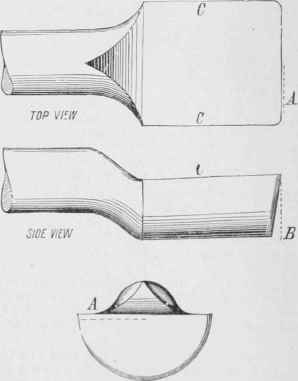
Km, . 1. -Half-Round Bits
In Fig. 2 is shown A, a boring bar; B B is the sliding head; C C is the bore of the cylinder, and 1, 2, and 3 are tools in the positions shown. D DD are projections in the bore of the cylinder, causing an excessive amount of duty to be placed upon the cutters, as sometimes occurs when a cut of medium depth has been started. Such a cut increases on one side of the bore of the work until, becoming excessive, it causes the bar to tremble and the cutters to chatter. In such a case, tool and position No. 1 would not be relieved of any duty, though it spring to a considerable degree; because the bar would spring in the direction denoted by the dotted line and arrow E, while the spring of the tool itself would be in the direction of the arrow, F. The tendency of the spring of the bar is to force the tool deeper into the cut instead of relieving it; while the tendency of the spring of the tool will scarcely affect the depth of the cut. Tool and position No. 2 would cause the bar to spring in the direction of the dotted line and arrow G, and the tool itself to spring in the direction of H, the spring of the bar being in a direction to increase, and that of the tool to diminish, the cut. Tool and position No. 3 would, however, place the spring of the bar in a direction which would scarcely affect the depth of the cut, while the spring of the tool itself would be in a direction to give decided relief by springing away from its excessive duty. It must be borne in mind that even a stout bar of medium length will spring considerably from an ordinary roughing-out cut, though the latter be of an equal depth all round the bore, and from end to end of the work. Position No. 3, in Fig. 2, then, is decidedly preferable for the roughing-out cuts. In the finishing cuts, which should be very light ones, neither the bar nor the tool is so much affected by springing; but even here position No. 3 maintains its superiority, because, the tool being pulled, it operates somewhat as a scraper (though it may be as keen in shape as the other tools), and hence it cuts more smoothly. It possesses, it is true, the defect that the distance from the cutting point stands further out from the holding-clarnp, and the tool is hence more apt to spring; and in cases where the diameter of the sliding head is muchless than that of the hole to be bored, this defect may possess importance, and then position No. 2 may be preferable; but it is an error to employ a bar of small diameter compared to that of the work.
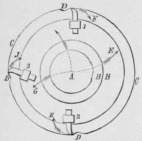
Fig. 2-Spring Of Boring Tools
To obtain the very best and most rapid result, there should be but little space between the sliding head and the bore of the work; the bar itself should be as stout as is practicable, leaving the sliding head of sufficient strength; and if the bar revolves in journals, these should be of large diameter and with ample facilities for taking up both the diametrical and end play of the boxes, since the one steadies the bar while it is performing boring duty, and the other while it is facing off end faces, as for cylinder-cover joints.
Continue to:
My Books

