The Machine Shop. Part 4
Description
This section is from the "The Construction Of The Modern Locomotive" book, by George Hughes. Also see Amazon: The Construction Of The Modern Locomotive.
The Machine Shop. Part 4
In the fixing of this, advantage is taken of the holes for the crank pins, which have been bored out, so that by fixing standard mandrils in the T slots of the table, these rods are very expeditiously set; moreover, there is no encumbrance whatever to impede the progress of the feed when once started. Fig. 277 is a aide elevation and plan of the former and its stand. After these operations have been accomplished, the bolt and oil syphon holes are drilled and rimered out, which finishes the machine work. Nothing now remains hut to finish on the fitting bench, by coupling up the brasses and straps to the connecting rods and forcing in the bushes of the coupling rods, then all is ready for the erecting shop. The valve rods and anchor links. Figs. 233-35, p. 140, are first milled upon each side of the boss, and then the pin holes drilled two at once by the aid of a jacket, with case-hardened bushes and a twist drill. Afterwards they are put on a 2-inch mandril in the centre of the table of a vertical milling machine and worked round the bosses.


Fig. 277.

Then they are placed upon the table of a small profiling machine, and milled upon the flats by the aid of a jacket, which is secured to the table and made specially for this work; it is of sufficient depth and width to receive the ends of two links - Fig. 278 clearly showing this. They are then dropped upon a pin fixed in the same table at each end, and secured with nut and washer and milled round the edges, cutters being used which leave all fillets and radii alike.
The stirrup link, Figs. 237-239, p. 142 for the Joy motion, after being marked out is placed upon a vertical milling machine, and the outside faces milled up by parallel traverse of the table, then the pin holes are drilled and again dropped upon the milling table, and the profile edges gone over This, as well as the swing links and all other work with sides not parallel but straight tapers, is set so that one side is made parallel with the cutter or the traverse of the table, milled, and then the other side done. After each side has been machined, it is put on to the table of a vertical cutter having circumferential movement, which mills the circular ends or round corners. The only rough portion remaining is between the forks, and this is machined by using the jacket shown in plan and elevation, Fig. 279, and section through A B, Fig. 280, which is held to the table by aid of the T slots, and the cutter passes to its work after a very rapid fixing. Finally, Fig. 281 (refer also p. 159, Fig. 253) shows, perhaps as well as any previous illustration, the ease with which a difficult job for a slotting or shaping machine is done.
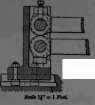
Fig. 278.
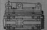
Fig. 279.
Scale 1«" = 1 Foot.

Fig. 280.
Scale 1«" = 1 Foot.

Fig. 281.
Scale ¾" = 1 Foot.
Now that milling as a class of work has been dispensed with, it may be advantageous to follow the rest of the machine shop practice in a more or less precise order, such as frames and appendages, wheels and axles, cylinders and motion, etc. Fig. 282 shows the frame plate as it is received from the mill floor, also as it leaves the slotting machine, the centre lines of buffer, cylinders, axles, and the drilled clearance holes for the slotting tool All frames are first put on to the levelling table, tried over, marked and straightened by the aid of two hydraulic jacks, which are attached separately on carriages, or conjointly on one carriage, having longitudinal movement, the jack itself being capable of traversing transversely. Dealing with frames, it has been found preferable to dispense with the thin template, as it is so liable to get out of truth by constant use, such as buckling, no matter how well it is braced with angle irons, which are always more or less in the way, and the means adopted in its place is to mark out one frame, which is a two hours' job, and proceed in a somewhat similar manner to that described in the boiler shop practice, p. 7. This serves as a jacket for drilling and marking out, until the last batch is finished, They are slotted at a three-head slotting machine, four pairs - or eight frames - at once, each head having a drilling arrangement for a slotting tool clearance, the plates being first roughed out by the three parting tools, which are ⅞ inch or 1 inch wide at the point, leaving ⅛ inch for finishing. All bolts and cramps are slackened previously to finishing, to allow the elimination of any spring or buckle that may be held by internal strain, and released by the removal of the roughing-out pieces.
They are then finished, twelve strokes per minute, and 1/16 inch feed per stroke, after which they are removed to the drilling machine, which really consists of two radial arms, 18 feet 4 inches apart, the table for each being a carriage or trolley on an 18-inch gauge capable of free traverse, which enables the driller to give the frames longitudinal movement as the work proceeds, the whole process being exactly similar to that adopted for the barrel plates in the boiler shop, and previously referred to. Some frames require a set inwards at the smoke-box end, for radial-wheel clearance, and this is done on the straightening table by the aforementioned hydraulic jacks. The cross stay, motion plate, and the foot or drag plate are first machined on an ending or double-headed rotary facing machine, which will face up anything that goes between the frames of an engine. A little margin is allowed for adjustment of each head, which are 2 feet in diameter, there being twenty tools fixed in each disc, by wedge bolts. The machine is speeded to 25 feet per minute, and 1-inch feed for steel castings, increased to 1¬ inch for iron castings. All the necessary holes for bolting or riveting to the frames, slide-bar brackets, anchor links, etc, are drilled and bored by the aid of jackets, to standard, and the steel castings are seat to the grinder to be scaled. The foot or drag plate has the bearing for the tender-buffer rubbing blocks machined by an end milling or facing cutter. These blocks are case-hardened mild steel plates, 1« inch thick. It is then planed for the various brackets, for holding such as the brake-shaft carriers, etc, everything being finished to template size. Illustrations of these castings are given on p. 60, Figs. 66-68, p. 88, Figs. 87 and 103.

Continue to:
My Books

