The Machine Shop. Part 5
Description
This section is from the "The Construction Of The Modern Locomotive" book, by George Hughes. Also see Amazon: The Construction Of The Modern Locomotive.
The Machine Shop. Part 5
The hornblocks, see Fig. 98, p. 90, are first planed for the frame seating to template, a quantity at once, at 21 feet per minute, and then sent to a vertical milling machine for machining the axle-box seating, and the space for the adjusting wedge. This is accomplished by placing the casting planed face downwards upon a jacket, which at once fixes it, and then passing a cylindrical cutter over each side, which covers the whole surface. Afterwards this is removed and a facing cutter placed upon the same spindle to cut out the groove for the adjusting wedge. It is then slotted at the bottom for the keep and also for the wedge bolt hole. The holes are then drilled to 1-inch standard, through the cast-iron jacket, Fig. 283, winch has hardened bushes. It then goes to the bench, and the wedge, keep, etc. are all put together and sent in sets to the erecting shop.
The axle-boxes, shown in Figs. 157-161, p. 112, are made of phosphor bronze. Steel castings are also used, case-hardened wrought iron being a tiling of the past. The bronze boxes are first put on to the planing machine twenty-two at once, in two rows of eleven each, upon parallel strips, and secured to the tables by bolting to the T slots, for machining to gauge between the jaws for the keeps, the cutting operation being per formed from the cross slide, and the feed vertical. After the keeps have been planed, they are dropped in a good fit, and the 1« inch hole opened out for the mild steel case-hardened pin which carries the spring link. The boxes are again fixed on the planing machine, attached to a double angle plate, which is secured to the table, and brings them within range of the tool boxes upon each upright, besides those on the cross side, thus machining one horn seating and one face of twelve boxes, six on each side, at one operation, this method being repeated for the other seating and side. Afterwards they are taken to the bench, and the lids or caps to the oil and tallow boxes fitted on. In passing to the erecting shop, they stop at a handy little shaping machine which cute the oil grooves in the horn seating (a much neater and quicker job than chipping); and here it may be mentioned that many oil grooves in various seatings, &c„ such as slide blocks, are milled in at a quick rate by a small circular cutter. The boxes are bored six at once in a machine located near the erectors, and dealt with in that section. The speed of the table for planing is 25 feet per minute, and the feed 1/16 inch for each stroke. This speed, compared with that for turning brass, appears very low, but it must be remembered that wear and tear, which takes place in a high degree upon every reversal of the table, would be accelerated by any increment of speed. The crank axles, see Figs. 219-222, p. 130, are first put in the lathe, square-cent red, cut to length over all, and rough turned on the wheel seat and journal, leaving ⅛ inch for finishing, and also a square ridge in the fillets A, Fig. 284, to assist in the adjustment of the quadrant centra plates.

They are then placed on the setting-out table to ascertain the error, if any, in the twist, which is never more than ¬ inch. Every crank must be tested for this, and the quadrants accurately set accordingly, for the finished crank depends entirely upon the initial adjustment and firm fixing of these quadrant centres. The error itself is discovered by setting level the horizontal sweep, then fixing a square up against the ridges in the fillets A, and marking at the top of the vertical sweep upon each side, which shows the error to be the formation of more or less than the right angle. This is then divided between the two throws, by canting the horizontal sweep in the required direction, which altera slightly the position of the centre lines, and is finally eliminated by the slotting machine.
The error is very seldom sufficient to necessitate the return of the crank to the forge for readjustment; for the twisting template is better looked after than to admit of this. The quadrant centres are then adjusted by the set screws and rigidly keyed up, care being taken that they do not move during this operation. Fig. 284 gives the longitudinal elevation and Fig. 285 the end elevation of these centres, with jack bolt complete. The whole arrangement is then placed in the crank sweep milling machine, which, inter alia, consists of a disc with about eighty ordinary tools, wedged in the periphery, 4 feet 2 inches in diameter, and having a circular speed of 10 feet per minute, The feed can be adjusted so that as a less number of cutters are engaged simultaneously, it can be increased, and may average 6 inches per hour circumferential speed of feed, the centre of the crank pin for the radius; or in other words, the whole space may be removed in from eight to ten hours, leaving ⅛ inch for finishing the crank pin. This machine has been described upon more than one occasion, and is well known. The crank is then removed to the finishing lathe and completed, four tools being used, that is, two back and two front slide rests. The webs are then slotted round, there being two tools in separate boxes on the same head, each the required distance apart, which arrangement necessitates only a 5-inch stroke, twelve per minute.
It is fixed for slotting by simply dropping into a box, Fig. 286, which is fixed and secured to the tables, and has a graduated scale which facilitates any required adjustment. The straight axle, Fig. 226, p. 133, is turned accurately to gauges, and the same speed is employed as for the pins and journals of the cranks, viz. 22 feet per minute, with a feed of ⅜ inch to « inch per minute. The key seatings are milled out at one cut on a specially arranged horizontal machine. They then have the wheels pressed on at the wheel press, a total of one ton to two tons per square inch on a 9-inch ram being employed. This range of pressure is not in any way due to inaccuracy of turning or boring, because every axle and wheel seat is turned and bored upon every occasion to gauge and template, as near as any operator's touch will permit; but mostly to a difference in materials, cast iron of course requiring the least, and in steel castings some wheel seats may be harder than others, and a little extra resistance in the wheel seat makes a large difference on the pressure of the ram. Afterwards the wheels are keyed up, the crank pins for the outside rods fixed, and the whole sent to the erectors.
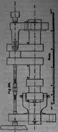
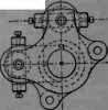
Fig. 285.

Fig. 286 .
Continue to:
My Books

