Plumbing In Seventy-Second Street Houses, New York
Description
This section is from the book "American Plumbing Practice", by The Engineering Record. Also available from Amazon: Plumbing: A working manual of American plumbing practice.
Plumbing In Seventy-Second Street Houses, New York
(Published In 1891.)
The plumbing of two new houses on West Seventy-second Street, New York, provides for an unusually complete control of the hot water, which may be supplied from either or both of two boilers to any or all of eight subdivisions of the house at will. There are also some special details designed for this work by Paul S. Bolger, who executed the plumbing and gas-fitting. The largest house is four stories high with a basement and cellar, and its three upper floors are divided by central halls, to each side of which the water supply is independent.
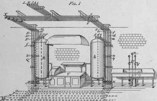
Figure 1 shows the two 90-gallon boilers B and C, which are heated from water-backs in the kitchen range R. Both of them are at present supplied with water under street pressure, but it is intended that either of them shall be supplied from a roof tank if the city pressure becomes insufficient. Cold water is received from the street through pipe C and from the tank through pipe A. To connect either boiler, as B, with tank pressure, its supply pipe D must have the street pressure cut off and tank pressure admitted by closing its valve at Z and opening its valve at X. Delivery pipe E and circulation pipe G must be cut off from the street pressure by closing their valves at X and Z, and the supply, delivery, and circulation pipes d, f, and h, of street pressure boiler b, must be cut off from tank pressure by closing their valves at x and z. Then boiler B will deliver through pipe F and boiler b through pipe e, pipes E and f and circulation pipes G and h being cut out. By reversing the valves, boilers B and b would work under street and tank pressures respectively, and pipes e, F, g, H would be cut out.
I is street hot, J is tank hot, L is street circulation, and K is tank circulation for the upper stories. M is the street hot and N is the tank hot supply to the first floor and basement fixtures. By closing the valves at X and x on pipes D and d, and opening all others, both boilers are put under street pressure, or by closing the valves on C, at Z and z, and opening all others, both are put under tank pressure.
The circulation pipes G g and H h are united below the kitchen floor to pipes O for the tank and P for the street pressure systems, and they and the boilers may be emptied through valves at Z and z, and in the cellar. Q and q are check valves to prevent the escape of tank water into the street mains. U, u, etc. are eight unions. All the pipes, boilers, fixtures, and other metal-work are nickel-plated, and the kitchen walls are finished with white ceramic tiles.
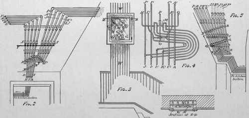
Figure 2 shows the continuation into an adjacent hall of the tank, hot-water, and circulation pipes A, I, J, and K L, and their division into two groups of risers, one supplying each side of the house. Pipe A1 is connected with the tank, and both A1 and A2 serve for general tank supply. Each group of risers has from the foot of the vertical shaft an additional pips C1 C2 (not shown here), supplying cold water under street pressure. Y is a drip pipe and S S are 10 special valves through which the riser lines may be emptied. B B are five unions and D D are 10 special angle valves controlling the riser lines.
Figure 3 shows a glass cabinet G, on the wall of the back stairway, which contains a cut-off M and three-way cock O for connecting the fixtures on one side of the second floor, with either the tank or street pressure system. The risers are carried in a wall shaft X, accessible throughout through panels W W, but are deflected to one side at V, just below the cut off, to afford more room for connections, as shown in diagram, Fig. 4. L1 is the street and K1 the tank pressure circulation; J is the tank and I the street pressure hot-water supply, and A1 the tank and C1 the street pressure cold-water supply; H is the hot-water and Q the cold-water distribution to the second-floor fixtures, and P is the return circulation pipe from them.
When the cut-off handles are turned down, the corresponding pipes H and Q are connected with tank pressure, when turned up, as shown, they are connected with the street pressure. When the handle of the three-way cock O is turned to the right, as shown, the circulation is under the tank-pressure system; it is under the street-pressure system, however, when it is turned to the left. There are six switch arrangements like the above, three in the back stairway halls for the second, third, and fourth stories of one side of the house, and three under the washbasins for the same stories on the other side of the house.
The system is essentially the same in the adjacent smaller house, except for the arrangement and connection of the supply lines in the basement hall, corresponding to Fig. 2. This is shown in Fig. 5, where the same reference letters have the same significance as in Fig. 2, and G G are ordinary valves controlling the rising lines, C C are 10 special drip cocks for emptying the rising lines into a pail, since it was not desirable to run a drip pipe from this point. The work throughout the house is well executed and is beautifully finished, corresponding with the costly materials and fixtures, but the most noticeable features are the symmetry and neatness in the pipe and valve work, as shown in Figs. 1, 2, and 5, where the unions, valves, connections, etc. are set in exact regular lines and the pipes compactly and attractively arranged.
PLUMBING IN SEVENTY-SECOND STREET HOUSES, NEW YORK CITY.
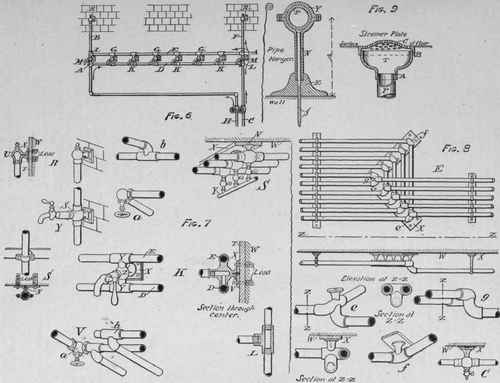
Figure 6 shows the hot and cold supplies, H and C, for a set of four laundry tubs, adjacent to the kitchen. Hot water flows into distributing pipe D and air chamber B, and cold water flows into distributing pipe E and air chamber F. A A are ordinary tees, but L L are tees with one branch left solid, as at L, Fig. 7. Faucets G and K, etc. are specially made for this work, as shown at K, Fig. 7, the sleeves Y Y being cast on ball Z, which has a waterway from the faucet to only one of the sleeves, this being set downwards at G G G and upwards at K K K. Ball Z has a flange bearing on escutcheon plate X, to which it is fastened by screw V, and the whole is secured to the wall W, which is faced with white ceramic tiles T.
At faucets M M the balls Z have the water through from one sleeve to the other. The tops of the air chambers R R are finished like those at the kitchen sink, Fig. 1. The ball U being finished and fastened to the wall similarly to Z, above described, as shown at R, Fig. 7. T, in Fig. 7, shows the connection of the kitchen sink faucets which have extra long and heavy barrels screwed into ball S, which is similar to that at M, Fig. 6, S, Fig. 7, is a detail of the wall fastenings at S, Fig. 1. The ceiling hangers in that Figure are the same, except that shank N is made longer.
V, Fig. 7, shows the arrangement of any two of the pipes at V, Fig. 2. The special corner valve a and tee-bend b are clearly shown at a and b, Fig. 7. S, Fig. 7, shows the connection of drip pipe Y, Fig. 2. E, Fig. 8, shows the arrangement at E, Fig. 5; e, /, and g show the details of special fittings at E ; C, Fig. 8, shows the drip cock at C, Fig. 5. In Figs. 7 and 8 the letters W, T, X, and V have the same meaning, and it will be seen that care was taken to secure uniformity and simplicity in their design, and to avoid unnecessary separate parts. The ball connections are all essentially similar, except that the internal waterways and the special bends, tees, and unions admit a very simple and close arrangement of intersecting pipes, while they dispense with separate additional hanger pieces, and secure strength and stiffness.
Figure 9 shows an adjustable pipe hanger and an adjustable floor strainer. The former was used where a single pipe was to be supported from a wooden joist or board. Its stem N was made long, and fitted the socket in the top of the escutcheon base E. The stem N was cut to any required length and fastened in position by a screw S, of any desired length to penetrate to the proper firmness. After S is driven pipe P is put in place and yoke Y screwed on. For lengths A, of less than 3½ inches, stem N and base E were cast in one piece, and for very long lengths of A stem N was screwed into base E, which was tapped to receive a screw in the bottom, as shown at S and in other details, Figs. 7 and 8.
In the strainer-plate, for bathroom flow wastes, etc., the brass waste pipe P has a flaring tap T and separate perforated cap C, and the two screw joints A and B afford sufficient play to adjust the cap exactly for a difference of an inch or more in the position of the floor slab, without altering the length of the pipe.
Continue to:
My Books

