Experiments On Siphonage. Severest Strain
Description
This section is from the book "Plumbing And Household Sanitation", by J. Pickering Putnam. Also available from Amazon: Plumbing and household sanitation.
Experiments On Siphonage. Severest Strain
Showing Aggregate Loss of Water in Traps in Fractions of an Inch After
Each Siphoning Action.
Number of | Each Test. | |||||||||
Traps Tested | 1 | 2 | 3 | 4 | 5 | 6 | 7 | 8 | 9 | 10 |
S-Trap Fig. 143 1½ in. Seal 10 ft. Vent & One Return Bend | Seal Broken | Trap Emptied* | ||||||||
4-inch Pot Fig. 144 3¼ in. Seal | 2 in. out | 2 1-2 in. out | 2 3-4 in. out | Seal Broken | ||||||
4 inch Pot 20 ft. of Vent Pipe & 5 Return Bends | 3-4 in. out | 1 in. out | 1 1-2 | 1 3-4 | 2 | 2 1-4 | 2 3-8 | do. | do. | do |
Long Trap Fig. 139 | Seal Broken | |||||||||
S-Trap 2½ ft. Seal | Seal Broken | |||||||||
S-Trap 4½ ft. Seal | Seal Broken | |||||||||
S-Trap 6½ ft. Seal | All but 10 in. out | All but 6 in. out | do. | do. | do. | do. | ||||
13 in. Square Trap. Fig. 193 | 5-16 in. out | 11-32in. out | 3-8 in. out | do. | do. | do. | do. | do. | do. | do. |
13 in. Square Trap. Fig. 141 | 1-4 in. out | 3-8 in. out | do. | do. | do. | do. | do. | do. | ||
13 in. Square Trap. Fig. 147 | 1-16 in. out | do. | 1-8 in. out | do. | do. | do. | do. | do. | do. | do. |
13 in. Spiral Trap. Fig. 178 | 3-8 in. out | 1-2 in. out | 17-32 in. out | do. | do. | do. | do. | do. | do. | do. |
10½ Spiral Trap. Fig. 183 | 1-2 in. out | do. | do. | do. | do. | do. | ||||
10½ in. Spiral Fig. 180 | 1-2 in. out | 9-16 out | do. | do. | do. | do. | do. | |||
8¼ in. Spiral | 1-2 in. out | 3-8 in. out | 7-16 in. out | do. | do. | do. | do. | do. | do. | do. |
7 in. Spiral | 1-2 in. out | do. | do. | do. | do. | do. | do. | do. | do. | do. |
6¼ in. Spiral | 1-2 in. out | do. | 9 16 in.out | 5-8 in.out | do. | do. | do. | do. | do. | do. |
6 in. Spiral | 3-4 in. out | 7-8 in. out | 1 | do. | ||||||
*Only 1-8 inch of water left in bottom of Trap.
and much more powerful than any that can be brought to bear upon it in plumbing practice.
This same statement holds good down to the six inch size, the only difference being that the amount of water forced out of the reservoir chamber by the strains will be slightly greater in the smaller than in the larger sizes, as will be seen by reading the table. The two smaller sizes, namely, the 7 inch and the 6 inch, will resist any siphoning action, however long continued, which can be encountered in actual plumbing practice.
By slightly increasing the depth of the trap, in these smaller sizes, however, the resistance can be made to approximate that of the largest sizes. Thus by increasing the depth of the 7 inch trap by half an inch its resistance can be made substantially equal to that of the 10 inch and the 13 inch traps, and by increasing the depth of the 6 inch trap by an inch the same result can be attained in this case.
(2) The variations in arrangement of the partitions shown in the various figures given above, do not essentially affect their power of resistance to siphonage nor the cost of their construction.
Figs. 162 and 163 show two other arrangements of the partitions. The corners of the partitions may be rounded as shown in these drawings without greatly affecting the resistance of the trap, a slight increase in the length of the water-way fully restoring any loss of area thus occasioned.
Fig. 164 shows four ordinary S traps connected together.
I have drawn them for the purpose of comparison with Fig. 163. Such an arrangement of S traps would, of course, result in "air binding." But by venting them at the crown this is obviated.
Now the only difference between these two arrangements is that in Fig. 164 the S traps are placed vertically and in Fig. 163 they are placed horizontally. The forms and sizes of the traps in both cases are absolutely the same. But the entire character of the S trap has by this simple change of position become marvelously and radically altered.
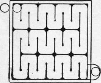
Fig. 162. Another arrangement of the partitions.

Fig. 163. S-traps placed horizontally.

Fig. 164. S-traps placed vertically.
In its ordinary vertical position the trap is now known to be utterly unreliable and therefore in effect worthless, presenting, as it does, the feeblest possible resistance to all the adverse influences which tend to destroy a water seal in plumbing, and for this reason the common S or siphon trap should never be used except for water closet seals, and then only under conditions of arrangement which will render their seals secure and reliable. In its horizontal position, on the contrary, it becomes absolutely invulnerable, and acquires all the qualities to be desired.
Thus the feat of rendering an S trap antisiphon without the aid of a vent pipe, as claimed at the beginning of this chapter, has been accomplished. By this treatment our S trap becomes in effect vented through its own inlet pipe, whereby the entire volume of fresh air needed to supply the strongest siphonage ever encountered and to ventilate the waste pipe system is made to pass directly through the body of the trap itself without the slightest danger of destroying its seal in its passage.
(3) We find, however, that the free and rapid discharge of the waste water in normal use is diminished in proportioi as the turns required in its passage through the trap are abrupt and varied.
Thus the traps shown in Figs. 147 and 162 retard the flow more than those shown in Figs. 138 and 141, and the opportunities for sediment deposit are greater in the latter than in the former. Hence of these forms the former have two important advantages.
Experiments were also made on horizontal traps with combinations of curved and straight partitions as shown in Figs. 165 to 177, inclusive. They showed about the same power of resistance as the traps having all rectangular partitions, but were, for the same reasons, subject to the same defects.

Fig. 165.

Fig. 166.
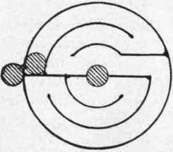
Fig. 167.

Fig. 168.

Fig. 169.

Fig. 170.

Fig. 171.
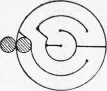
Fig. 172.

Continue to:
My Books

